Shijiazhuang, Hebei, Chinasales@kaifil.com
KAIFIL
Filter media rolls and sheets

Electroformed nickel screens

Electroformed nickel screens are deposited around a patterned tool to create thin, repeatable aperture fields. They are distinct from stainless woven cloth and photo-etched foil in material and pore profile.

Etched and electroformed screens
Construction
Electroformed nickel
Aperture geometry
Round / square / shaped openings
Edge / connection
Loose screen / framed screen / backed insert
Release checks
Inspection of the complete screen

Share a drawing, reference sample or application requirements to discuss the configuration.

Specifications

Electroformed nickel screens
ParameterSpecificationNotes
ConstructionElectroformed nickelNickel deposited on a patterned mandrel and released as a screen
Aperture geometryRound / square / shaped openingsThe working-face opening, outlet profile and deposited thickness define the aperture.
Edge / connectionLoose screen / framed screen / backed insertThe electroformed sheet defines the aperture field. The frame or backing defines the supported span, locating surfaces and sealing perimeter.
Release checksInspection of the complete screen—

Product details

Electroformed nickel screens: construction

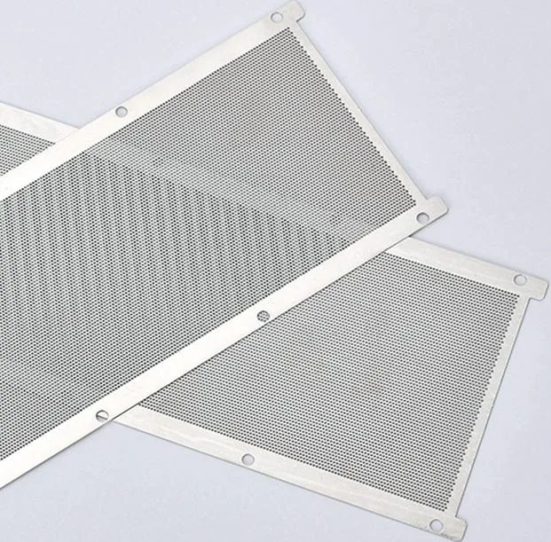
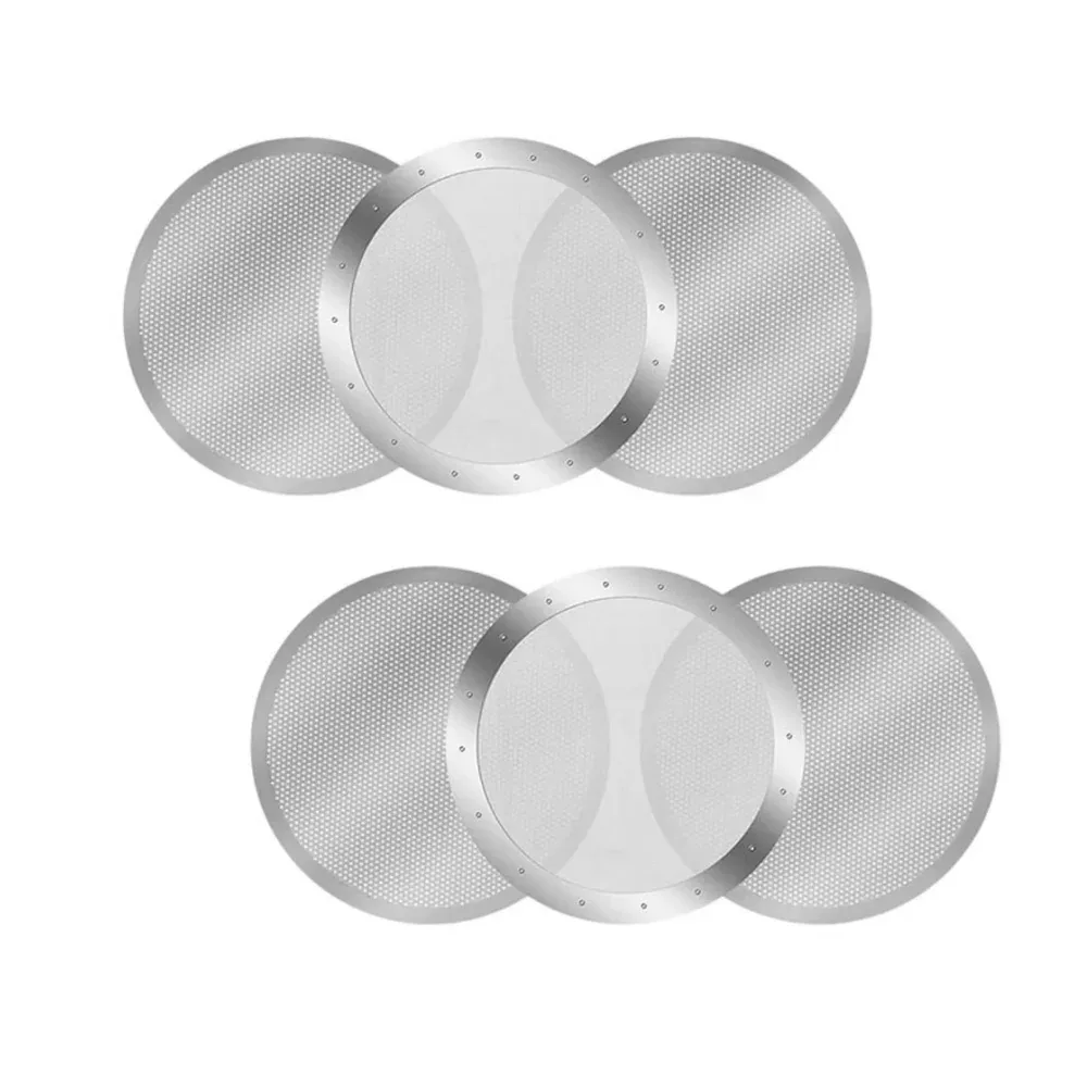
Metal is grown on a mandrel or patterned substrate, then released as a screen with a controlled hole or slot shape. The process can create smooth, tapered passages for a defined flow direction. Electroformed nickel screens offer controlled round, square or shaped apertures. Deposited thickness, ligament width and a backing frame are selected together for the aperture pattern and supported span.
Working face, thickness and support

The drawing identifies the inlet face, outlet profile, deposited thickness, pitch and ligament width as one aperture construction. The solid border provides the mounting and sealing zone; a frame or backing defines the supported span. Specify the liquid or gas, cleaning chemistry and flow direction for the nickel screen and its support.

Inspection of the complete screen

Measure the opening at the identified face, the pattern pitch, deposited thickness and solid-border dimensions. Inspect unintended pinholes, continuity of the aperture field and edge integrity. Record flatness and the contact area of the frame or backing as separate assembly dimensions.

Laboratory test-sieve specifications

ISO 3310-3 covers electroformed-sheet test sieves with round or square apertures from 5–500 µm. ASTM E161 addresses electroformed material and test-sieve construction, using nickel or another metal suitable for electrodeposition. A laboratory sieve specification identifies the standard, aperture shape and nominal size, frame and support arrangement. A custom filter screen drawing defines its own working-face opening, deposited thickness, solid border and mounting interface.

Choose the manufacturing route

Choose the manufacturing route

ProcessMetal structureAperture definition
Electroformed nickelNickel deposited on a patterned mandrel and released as a screenWorking-face opening, deposited thickness and inlet/outlet profile.
Woven nickel meshNickel wires interlaced in warp and weft directionsWire pair, weave and count in each direction.
Photo-etched foilSolid foil patterned and chemically removed at the openingsFoil thickness, etched wall profile and remaining ligaments.
Electroformed test sieves: ISO 3310-3 aperture scope

Electroformed test sieves: ISO 3310-3 aperture scope

Aperture shapeStandard scopeUnitStandard and application
Round aperture5–500µmISO 3310-3:1990 · electroformed-sheet test sieves
Square aperture5–500µmISO 3310-3:1990 · electroformed-sheet test sieves
Ordering and production

Ordering and production

Supply itemOrder basis
Production lead time2–3 weeks after order and drawing confirmation.
Trial ordersSmall trial quantities for fit and process evaluation.
Regular production orders50 pieces or US$3,000 per order.
Quotation basisMaterial, finished dimensions, filter construction, connections and quantity.

Selection guide

Include these details when discussing your requirements.

Working face, thickness and support
The drawing identifies the inlet face, outlet profile, deposited thickness, pitch and ligament width as one aperture construction. The solid border provides the mounting and sealing zone; a frame or backing defines the supported span. Specify the liquid or gas, cleaning chemistry and flow direction for the nickel screen and its support.
Inspection of the complete screen
Measure the opening at the identified face, the pattern pitch, deposited thickness and solid-border dimensions. Inspect unintended pinholes, continuity of the aperture field and edge integrity. Record flatness and the contact area of the frame or backing as separate assembly dimensions.

Applications

Precision separation screens

Specify the working-face opening, outlet size or profile, thickness and flow direction together. These dimensions define the passage through the deposited metal.

Instrument protection

The electroformed sheet defines the aperture field. The frame or backing defines the supported span, locating surfaces and sealing perimeter.

Frequently asked questions

How is a tapered aperture specified?

Specify the working-face opening, outlet size or profile, thickness and flow direction together. These dimensions define the passage through the deposited metal.

How does the frame relate to the nickel screen?

The electroformed sheet defines the aperture field. The frame or backing defines the supported span, locating surfaces and sealing perimeter.

Technical enquiry

Define the dimensions, media, joints and inspection records before confirming the order.

Technical details (optional)
Selection inputs

WhatsApp

Search