
Shijiazhuang, Hebei, Chinasales@kaifil.com
KAIFIL
Demister pads and mesh blocks

Segmented demister pads

Numbered knitted-mesh demister segments with matched grids, joint contact and support layouts. Manway access, assembly dimensions and drainage details.

Metal wire mesh
Assembled pad
Vessel inside diameter, pad depth and support level
Individual segment
Outline, maximum diagonal, handling height and identification
Joints and restraints
Mesh contact, grid overlap, beams and retaining clips
Depth configurations
100 /150 mm pad depth; grids dimensioned separately

Share a drawing, reference sample or application requirements to discuss the configuration.

Product details

Construction and function

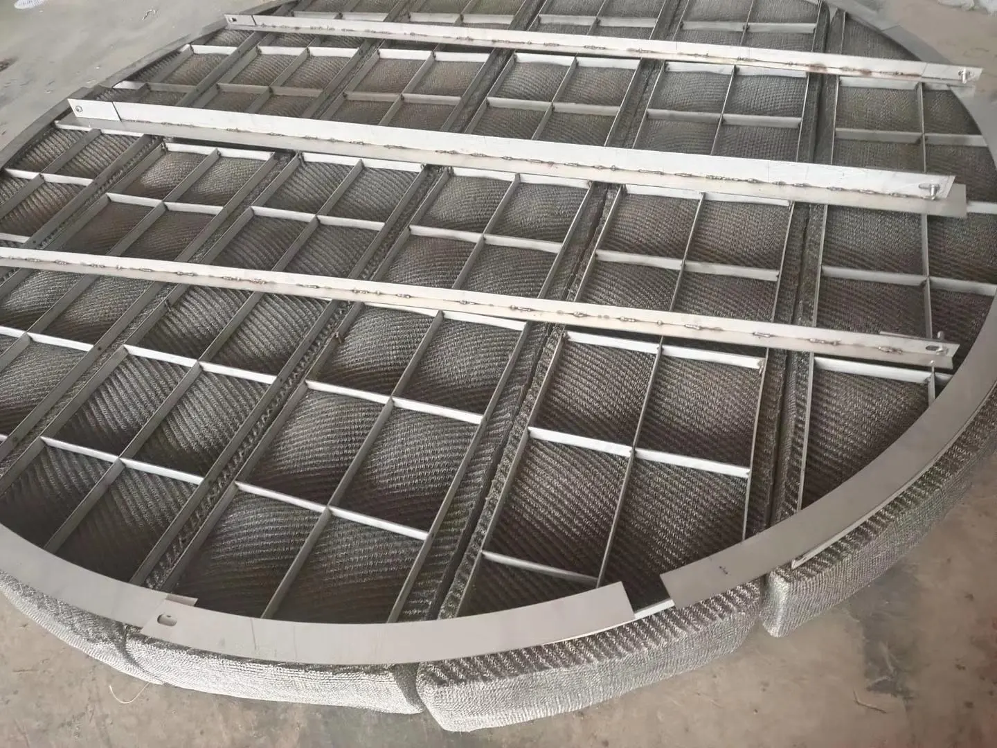
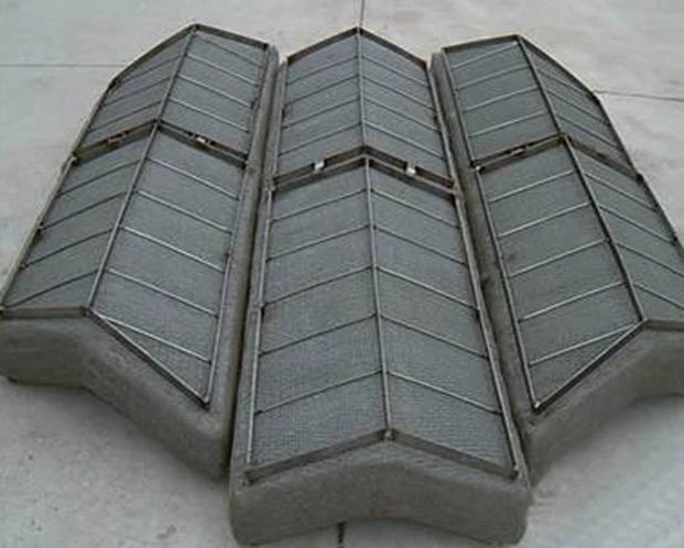
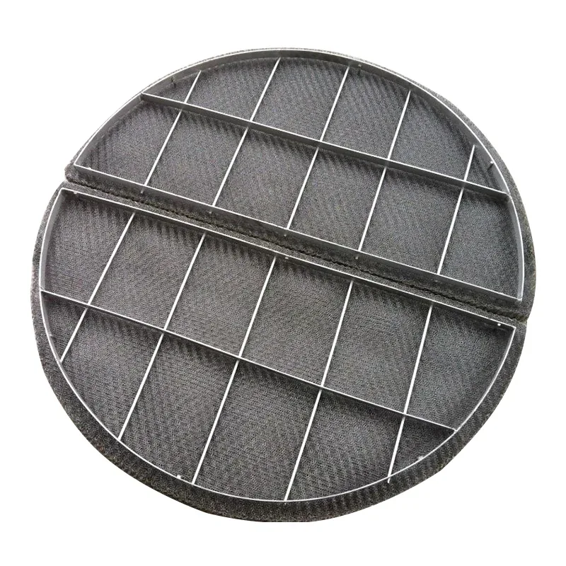
A segmented demister divides the knitted separation layer into pieces that pass through the vessel manway. Each segment carries its own mesh and retaining grid, while match marks identify its place in the assembled pad. Segment width, diagonal and handling height define access through the manway; assembled vessel diameter is a separate dimension.
Installation and inspection

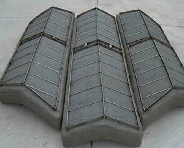
The layout sets support beams, grid overlaps, retaining clips and joints between adjacent mesh blocks. Continuous contact at those joints controls gas bypass. Installation follows the numbered layout, followed by inspection of joint contact, orientation, hold-downs and drainage space. Retrofit and large-vessel assemblies use the same complete pad geometry with a separately defined transport and installation split.

Shaped knitted-mesh sections with retaining support frames

Segment the pad around the manway and support grid

Lay out the pad as an installed assembly before setting segment widths. Each segment must pass the clear manway and handling route together with its grid or retaining frame. The full pad outline, segment transport envelope and support-beam locations are separate dimensions on the drawing.

Mark segment positions and the service face so the pad is reassembled in its intended order. Check grid-to-grid contacts and the perimeter against the vessel support. Preserve the mesh depth and drainage direction during lifting and packing. Keep dry mesh mass separate from the mass of grids, clamps and frames.

Component and interface schedule

Component and interface schedule

FeatureTechnical definition
Assembled padVessel inside diameter, pad depth and support level
Individual segmentOutline, maximum diagonal, handling height and identification
Joints and restraintsMesh contact, grid overlap, beams and retaining clips
Depth configurations100 /150 mm pad depth; grids dimensioned separately
Four-sector layout calculationØ1200 mm assembly in 4 sections; nominal quarter radius 600 mm
Segmented pad drawing and assembly checks

Segmented pad drawing and assembly checks

Component or stageFunctionDrawing or inspection definition
Installed outlineDefines the vessel fitPad diameter or length and width
Segment envelopeDefines entry through the manwayClear opening, grid size and handling route
Support and jointsCarry and locate the segmentsBeam positions, grid contacts and perimeter
Identification and drainagePreserve the installed orientationSegment marks, service face and drainage direction
Four-sector demister layout: defined geometry calculation

Four-sector demister layout: defined geometry calculation

QuantityValueUnitInput or calculation
Assembled circle diameter1200mmDefined circular layout input.
Equal sectors4sectorsFour equal quarter-circle sectors.
Sector radius600mm1200 / 2 = 600.
Maximum chord of an ideal quarter sector848.5mm600 × √2 = 848.5; grids and retaining frames have their own outer envelope.
Ordering and production

Ordering and production

Supply itemOrder basis
Production lead time2–3 weeks after order and drawing confirmation.
Trial ordersSmall trial quantities for fit and process evaluation.
Regular production orders50 pieces or US$3,000 per order.
Quotation basisMaterial, finished dimensions, filter construction, connections and quantity.

Applications

Vessel retrofit

Individual sections pass through the manway and reassemble on the internal supports.

Large separation vessels

Matched segment edges form one continuous separation layer across the vessel.

Specifications

Segmented demister pads
ParameterSpecificationNotes
Assembled padVessel inside diameter, pad depth and support level—
Individual segmentOutline, maximum diagonal, handling height and identification—
Joints and restraintsMesh contact, grid overlap, beams and retaining clips—
Depth configurations100 /150 mm pad depth; grids dimensioned separately—
Four-sector layout calculationØ1200; R600 mmThe 1200 mm circle and four equal sectors define this geometric calculation. Grid/frame dimensions and handling orientation define the delivered transport envelope.
Material304 / 316L stainless steel—

Selection guide

Include these details when discussing your requirements.

View specifications
Layout shown
Ø1200 mm assembly in 4 sections; nominal quarter radius 600 mm

Frequently asked questions

What defines the installed assembly?

The layout sets support beams, grid overlaps, retaining clips and joints between adjacent mesh blocks. Continuous contact at those joints controls gas bypass. Installation follows the numbered layout, followed by inspection of joint contact, orientation, hold-downs and drainage space. Retrofit and large-vessel assemblies use the same complete pad geometry with a separately defined transport and installation split.

How do the media and support work together?

A segmented demister divides the knitted separation layer into pieces that pass through the vessel manway. Each segment carries its own mesh and retaining grid, while match marks identify its place in the assembled pad. Segment width, diagonal and handling height define access through the manway; assembled vessel diameter is a separate dimension.
Technical enquiry

Define the dimensions, media, joints and inspection records before confirming the order.

Technical details (optional)
Selection inputs

WhatsApp

Search