Operating data with units
State actual gas flow in m³/h at operating pressure in bar absolute and temperature in °C. If flow is given in Nm³/h, include the reference temperature and pressure. Add gas and liquid density in kg/m³, liquid viscosity in mPa·s, surface tension in mN/m and entrained liquid loading in kg/h.
Installation dimensions
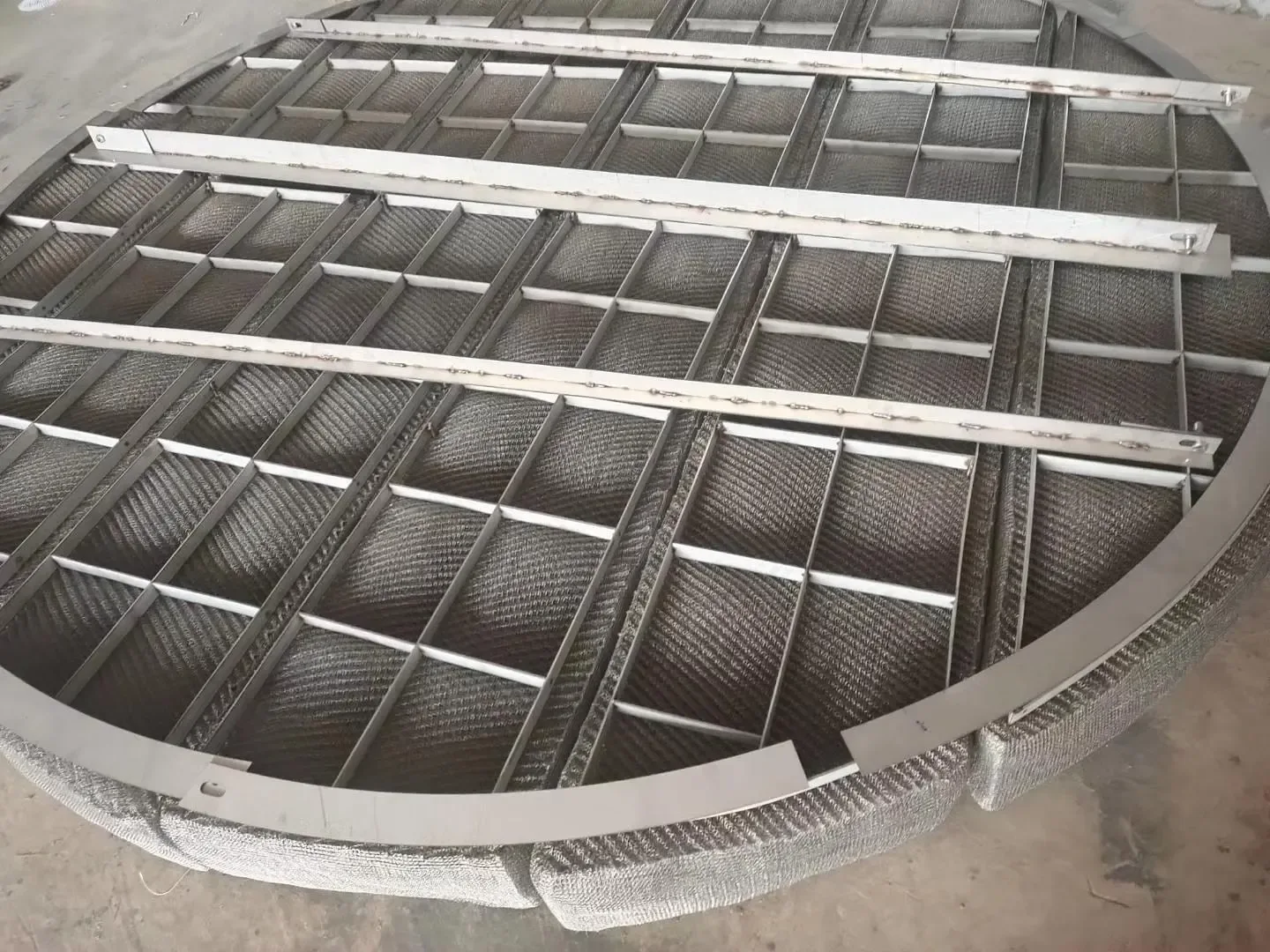
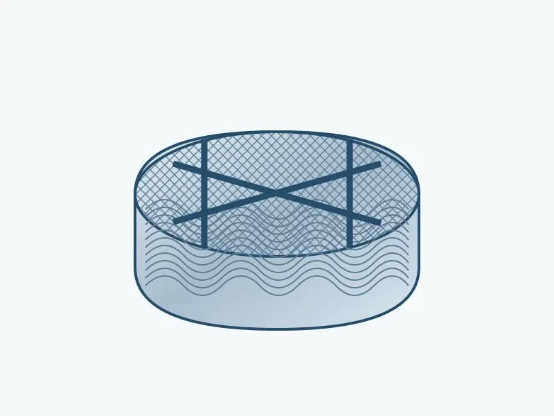
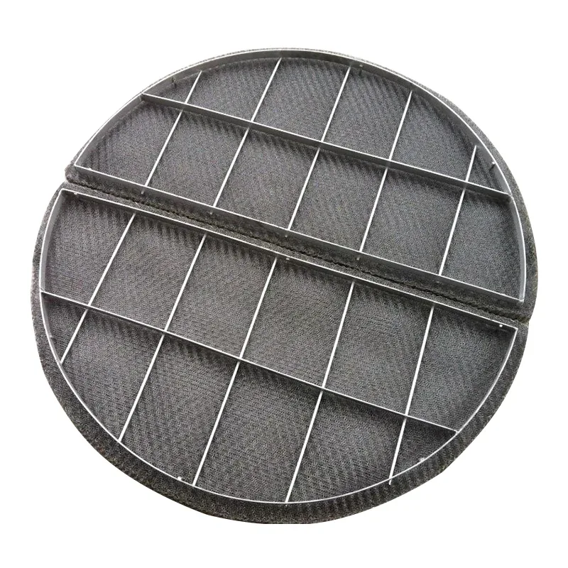
Provide vessel ID, pad diameter or length × width, pad depth, support-grid position and clear manway opening in mm. Show flow and drainage directions, available disengagement space, support beams, clamps and segment joints on the internals drawing.
Operating envelope and acceptance
Give minimum, normal and maximum gas and liquid loads, allowed pressure drop in mbar, outlet carryover target and its measurement basis. Record foaming, solids, corrosive condensate and the cleaning method so the pad can be configured for the duty.
Velocity calculation example
For 3,600 actual m³/h through a 1.0 m diameter circular flow area: Q = 1.0 m³/s, A = π × 1.0² / 4 = 0.7854 m² and superficial gas velocity = Q/A = 1.27 m/s. This calculates the operating velocity; pad selection also uses liquid loading, physical properties and the required separation duty.
Continue the specification
Related product forms
Relevant product categories
Connect operating flow to the installation drawing
Use the actual volumetric gas flow rate at operating pressure and temperature with the vessel flow area. Keep the reference conditions with the normalised volumetric flow rate for conversion. Mark whether the area is the empty vessel section or the effective area around internals, so the velocity calculation and the vessel drawing use the same basis.
Size each segment for the clear manway and the handling route, including its retaining grid. The assembled pad diameter and depth remain separate from the segment transport envelope. Identify support beams, clamps and drainage direction; record dry mesh mass separately from frame and grid mass.