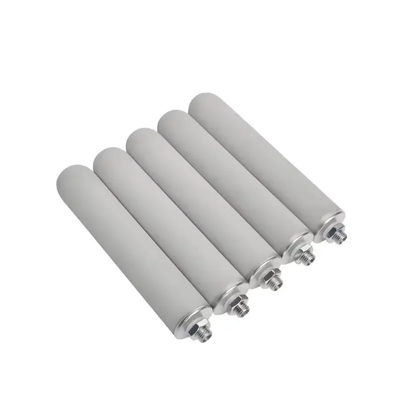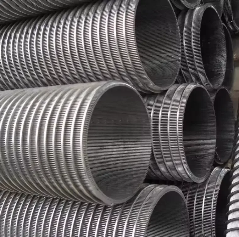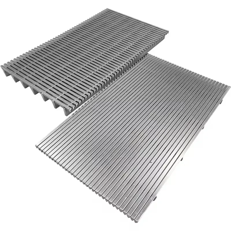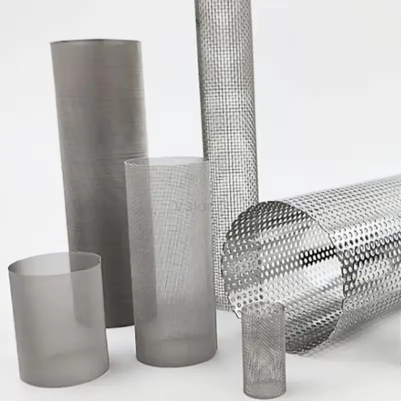

Start with the formation and completion
Identify the screened interval and whether the completion uses a standalone screen or a gravel pack. Supply a representative sand sample and its particle-size distribution. Where a gravel pack is planned, include its grading. Use these inputs to select candidates for retention and flow testing.
Identify the opening that retains sand
For a wire-wrapped jacket, specify the clear slot between adjacent profile wires at the working face, its tolerance and the measurement locations. For a composite screen, specify the retention layer and the inside-to-outside sequence of cloth, drainage and protective layers. Record base-pipe hole diameter and pattern, protective shroud openings and screen open area separately. For every open-area figure, name the component and the reference area or length.
Dimension the assembled screen
Put the nominal pipe size, actual base-pipe outside diameter, wall thickness and grade on the drawing. Give the screen jacket outside diameter and the maximum assembly outside diameter including couplings or end rings. Dimension active screened length and overall end-to-end length separately, and identify the end connections and unscreened sections. Label each dimension with its unit, such as mm or in for diameters and mm or m for lengths.
Agree on test methods and acceptance limits
Separate dimensional inspection of slots or holes from sand-retention testing. When comparing retention results, record the sample grading, test fluid, flow direction, flow rate and duration, plus the allowable mass of sand passed and the pressure-drop limit. Specify whether a micron rating refers to the cloth or the finished assembly and name its measurement method. Agree separately on the load direction and acceptance criteria for any collapse test.