Shijiazhuang, Hebei, Chinasales@kaifil.com
KAIFIL
Filter cylinders and tubes

Wedge wire filter cylinders

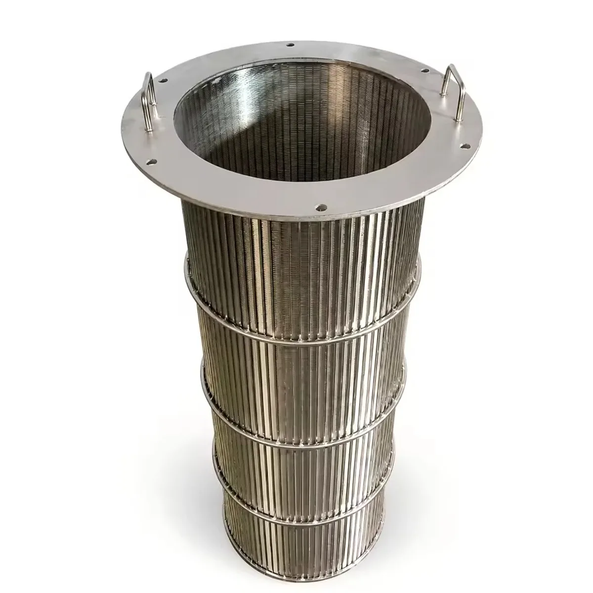
Continuous-slot wedge-wire cylinders provide a rigid screen surface for water intake, resin retention and process separation. Slot width, profile wire and support rods are designed around flow direction and load.

Wedge wire screens
Construction
Welded profile wire
Working-face slot opening
0.02–30 mm
Outside diameter
19–1000 mm
Cylinder length
≤6000 mm

Share a drawing, reference sample or application requirements to discuss the configuration.

Product details

Wedge wire filter cylinders: construction

Profile wire welded to support rods forms a continuous-slot cylinder. The narrow entrance faces incoming flow and the passage widens behind it. The slot selection series is 0.02–30 mm; profile section, rod spacing and the formed geometry define the construction.

Sizing and service for wedge wire filter cylinders

The cylinder drawing records finished inside or outside diameter, length, support-rod pitch and reinforcing rings. Plain, flanged, threaded and welded ends have distinct interfaces. Wire section and support layout follow the inward or outward loading direction, flow, process medium and cleaning cycle.

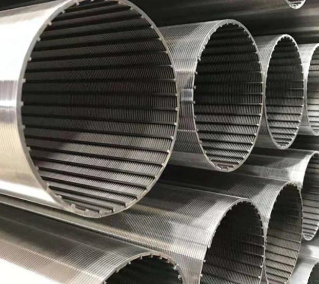
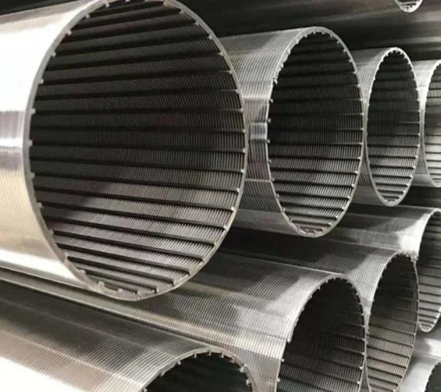
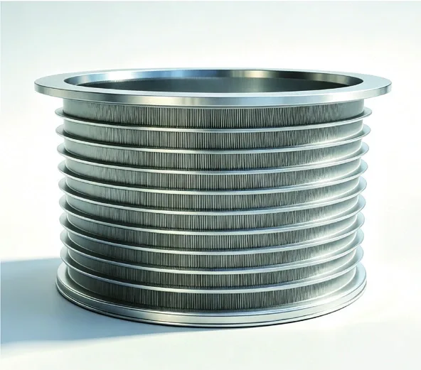
Cylindrical wedge-wire screens showing profile wires and their supporting structure.

Assembly inspection

The inspection record identifies the material, finished dimensions, joining surfaces and sealing interfaces. Measurements follow the installed geometry and the stated test conditions.

Integration with the filter assembly

The smooth profile-wire face is the screening surface and the support rods carry its load. Circumferential wire winding produces circumferential slots with axial supports; an axial-slot body places its screening wires and supports in a different orientation. The working face is positioned upstream for outside-in or inside-out filtration, and the cleaning mechanism follows that face. End rings, threads and flanges establish the installation interface. A standalone process cylinder is specified by its own seat and flow path; well-screen pipe assemblies have additional completion connections.

Specify the cylinder’s wire direction and active side

A cylindrical wedge-wire surface can use circumferential or longitudinal working wires, with a corresponding support arrangement. The flow drawing identifies the selected construction and its active face. Record the narrow slot on that face, then state the opposite-side drainage and support geometry.

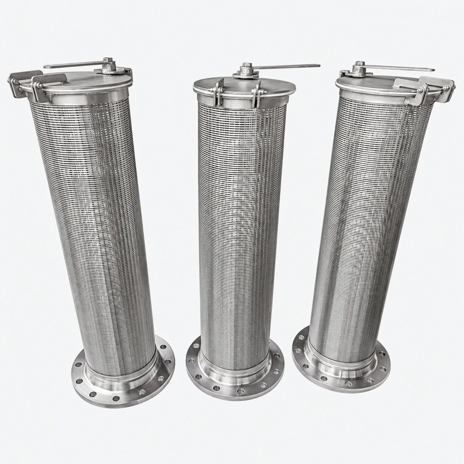
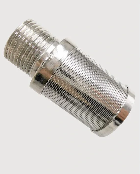
End rings, collars or flanges locate the cylinder and connect it to the equipment seat. They are separate from the active slot region. A filter nozzle adds a cap and mounting stem at a plate, while a full cylinder has its own end joints and active length; keep those interfaces distinct in replacement drawings.

Water well screens and sand-control specification

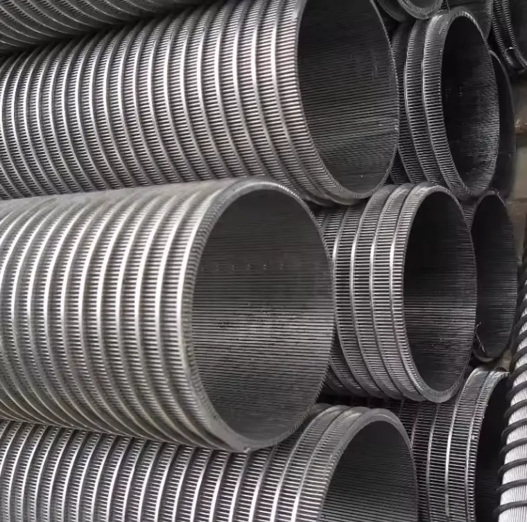
Water well screen and sand control describe an application of the continuous-slot cylinder. For a well-screen construction, specify the formation or gravel-pack particle-size analysis together with the required working-face slot, screen-section length, outside diameter and end connection. The drawing identifies the water-entry side and slot direction, and separates the slotted intake section from blank casing and connecting ends. Industrial strainer cylinders have their own support, mounting and flow arrangement; the well specification defines the cylindrical construction for its installation.

Assembly interface map

Assembly interface map

Component / interfaceDefined function and inspection
Working faceNarrow slot entrance faces incoming flow
Wire and support rodsProfile section, orientation and support pitch
End ring / thread / flangeInstalled diameter, alignment and seating
Normal and reverse flowSeparate loading directions for filtration and cleaning
InspectionSlot checks around the circumference; roundness and end alignment
Cylinder surface, support and ends

Cylinder surface, support and ends

ComponentTask in the systemDrawing or inspection detail
Working-wire directionSets the slot arrangementCircumferential or longitudinal construction
Active faceDefines the narrow slot openingSurface and service-flow arrow
Support membersHold the working wiresSection, spacing and drainage clearance
End ring or connectionLocates the cylinder in equipmentSeat, alignment, seal and active length
Cylinder surface, support and ends
Wedge wire filter cylinders — Dimension

Wedge wire filter cylinders — Dimension

DimensionValue (mm)
Working-face slot opening0.02–30
Outside diameter19–1000
Cylinder length≤6000

The cylinder series uses a selected V-wire profile and support layout. Slot width, wire section, diameter and length form a matched construction; the narrow working-face gap defines screening and the back of the slot widens for drainage.

V-wire profile

V-wire profile

Face width (mm)Profile height (mm)Relief angle (°)
0.81.96.5
1.22.510
1.52.513
1.83.210
1.84.76
2.33.813
3.25.113
3.37.98

The cylinder series uses a selected V-wire profile and support layout. Slot width, wire section, diameter and length form a matched construction; the narrow working-face gap defines screening and the back of the slot widens for drainage.

Ordering and production

Ordering and production

Supply itemOrder basis
Production lead time2–3 weeks after order and drawing confirmation.
Trial ordersSmall trial quantities for fit and process evaluation.
Regular production orders50 pieces or US$3,000 per order.
Quotation basisMaterial, finished dimensions, filter construction, connections and quantity.

Specifications

Wedge wire filter cylinders
ParameterSpecificationNotes
ConstructionWelded profile wire—
Working-face slot opening0.02–30 mmThe cylinder series uses a selected V-wire profile and support layout. Slot width, wire section, diameter and length form a matched construction; the narrow working-face gap defines screening and the back of the slot widens for drainage.
Outside diameter19–1000 mmThe cylinder series uses a selected V-wire profile and support layout. Slot width, wire section, diameter and length form a matched construction; the narrow working-face gap defines screening and the back of the slot widens for drainage.
Cylinder length≤6000 mmThe cylinder series uses a selected V-wire profile and support layout. Slot width, wire section, diameter and length form a matched construction; the narrow working-face gap defines screening and the back of the slot widens for drainage.
Installed dimensionsOD / ID / length to drawing—
Edge / connectionPlain · flanged · threaded—
Material options304 / 316L stainless steel; each filtering, support and end component has its own material designation.—
Operating dutyDefined for the installed assembly—
Release checksMaterial identity / finished dimensions / joining faces / sealing interfaces—
Exposed-face calculation0.5 slot / 2.0 face = 20 %—

Applications

Water-intake screens

Continuous slots and a rigid wall suit intake duty when slot, open area and hydraulic loading are calculated together.

Ion-exchange resin retention

A slot selected below the resin bead size can retain media while allowing distribution flow.

Backwashable process cylinders

Confirm reverse-flow loading and support geometry before specifying a self-supporting cylinder.

Selection guide

Include these details when discussing your requirements.

Confirm the installation
Finished OD or ID, length, support-rod pitch and any reinforcing rings to the installation drawing. Plain, flanged, threaded or welded end construction; state whether the profile-wire face is on the inside or outside.
Choose the filtering surface
Selected industrial wedge-wire constructions use slots from about 0.002 in (0.05 mm) upward; the required slot tolerance depends on profile, diameter and forming route.
Check the process duty
Confirm inward or outward differential pressure, flow, media chemistry and cleaning method before choosing the wire/rod section.
Set acceptance
Check slot gauges around the circumference, finished diameter, weld continuity and end alignment.

Frequently asked questions

How are the assembly components identified?

Working face: Narrow slot entrance faces incoming flow; Wire and support rods: Profile section, orientation and support pitch; End ring / thread / flange: Installed diameter, alignment and seating; Normal and reverse flow: Separate loading directions for filtration and cleaning; Inspection: Slot checks around the circumference; roundness and end alignment

Which installation details define this product?

The smooth profile-wire face is the screening surface and the support rods carry its load. Circumferential wire winding produces circumferential slots with axial supports; an axial-slot body places its screening wires and supports in a different orientation. The working face is positioned upstream for outside-in or inside-out filtration, and the cleaning mechanism follows that face. End rings, threads and flanges establish the installation interface. A standalone process cylinder is specified by its own seat and flow path; well-screen pipe assemblies have additional completion connections.

What does the finished-part inspection cover?

The inspection record identifies the material, finished dimensions, joining surfaces and sealing interfaces. Measurements follow the installed geometry and the stated test conditions.

Technical enquiry

Define the dimensions, media, joints and inspection records before confirming the order.

Technical details (optional)
Selection inputs

WhatsApp

Search