Shijiazhuang, Hebei, Chinasales@kaifil.com
KAIFIL
Filter media rolls and sheets

Perforated plate sintered mesh sheets

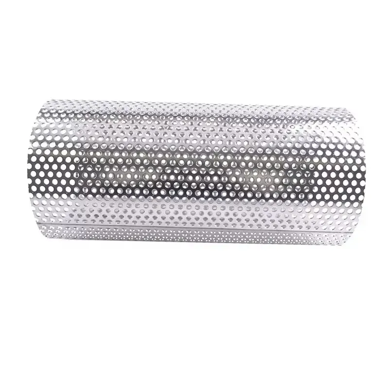
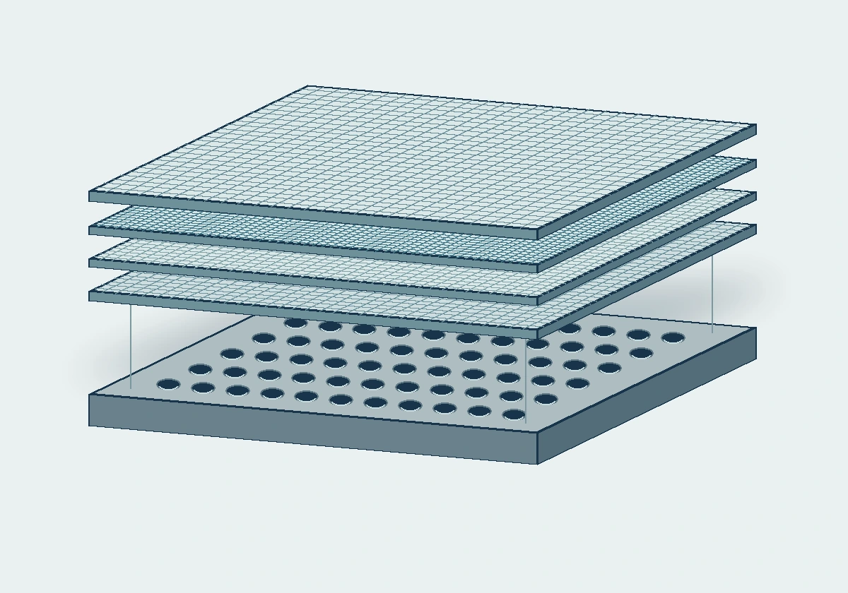
A perforated 316L stainless steel backing is sintered to woven wire mesh to form a rigid filter sheet. Specify the plate geometry and the mesh filtration grade separately.

Sintered metal filters and media
S04 sheet formats
500 × 1000 / 600 × 1200 / 1000 × 1200 mm
Support plate holes
Round or square
Support plate thickness
Per drawing
Filtering mesh grade
Per retention requirement

Share a drawing, reference sample or application requirements to discuss the configuration.

Specifications

Perforated plate sintered mesh sheets
ParameterSpecificationNotes
S04 sheet formats500 × 1000 / 600 × 1200 / 1000 × 1200 mmUse the part drawing to define the finished outline and tolerances.
Support plate holesRound or squareState the hole diameter or side length, pitch and hole layout. The pattern determines the open area of the backing.
Support plate thicknessPer drawingDimension the backing plate separately from the bonded laminate.
Filtering mesh gradePer retention requirementState the target grade in micrometres and the test method and acceptance criterion for measured retention.
Finished laminate thicknessPer layer sequenceSpecify total thickness separately, including where it is measured and the allowable tolerance.
Weld and seal landsUnperforated marginsDimension the solid width on each side of the joint and locate the seal and fixing points.

Materials: 316L stainless steel for the S04 sheet series.

Product details

How the composite is built

Sintering bonds the woven mesh to the perforated backing. The filtering mesh controls particle retention, while the plate supports the mesh around each opening. Protective and drainage meshes can be included in the layer sequence to suit the part.
Leave room to weld and seal

Show the unperforated lands, seam, weld limits and sealing face on the drawing. Put the weld on a solid land and allow for the transition between the active field and the joint. For rolled parts, show the location of the longitudinal seam relative to the ends and the mounting interface.

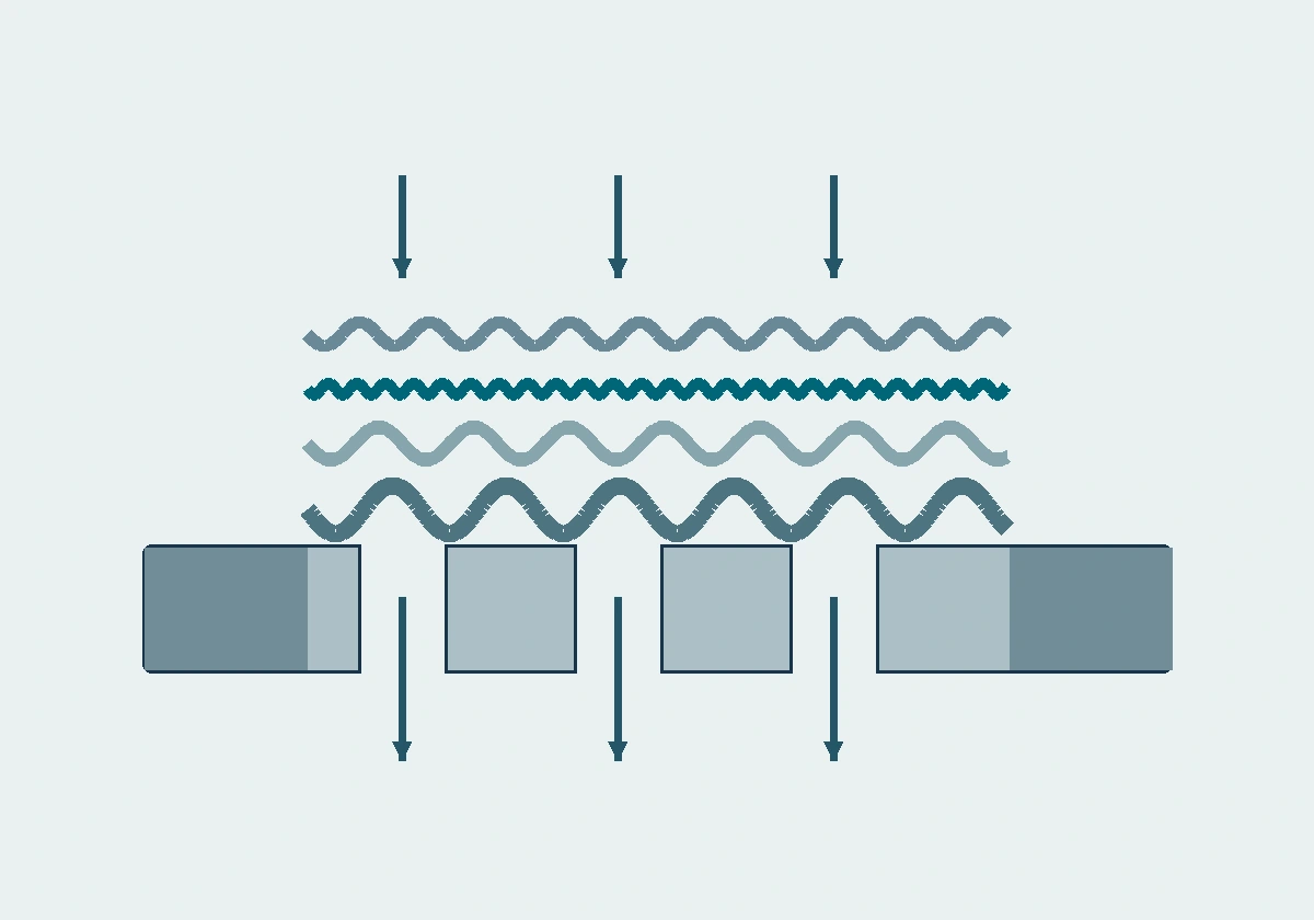
Cross-section through the protective mesh, fine filtering mesh, drainage layers and perforated plate with solid side margins.
Illustrative cross-section. From top to bottom, the protective mesh, fine filtering mesh and drainage layers sit on the perforated backing. The arrows show one flow direction. The drawing defines the installed orientation.

Applications

Water-treatment screens

Define where the housing supports the sheet and the area left open for filtration.

Backwashed process filters

Give the differential pressure in each direction and describe the cleaning cycle so the assembly can be specified for both loads.

Selection guide

Include these details when discussing your requirements.

Define the load path
Mark the upstream side, clear span and supports on the installed drawing. For rolled parts, identify inside-out or outside-in flow.
Allow for reverse loading
During backwash the pressure load reverses. Specify the maximum differential pressure in both directions and show how the perimeter, seams and ends are restrained.

Frequently asked questions

Which openings determine the filtration grade?

The fine mesh layer defines the retention target. The larger plate holes provide flow passages and determine how much of the mesh is supported.

How is the allowable differential pressure established?

Check the finished assembly using the plate geometry, unsupported span, mounting and flow direction. Include reverse load if the filter is backwashed.

Technical enquiry

Define the dimensions, media, joints and inspection records before confirming the order.

Technical details (optional)
Selection inputs

WhatsApp

Search