Three ways to build a connected metal pore network
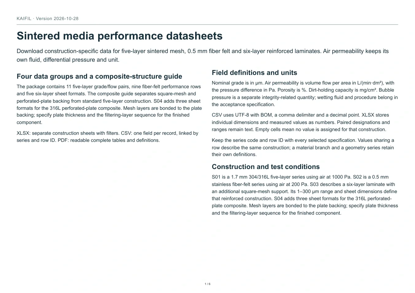
Sintering bonds metal contact points while retaining connected voids for flow. Woven mesh starts with ordered wire layers, fiber felt with a nonwoven web, and powder media with packed metal particles. These structures produce different pore paths and fabrication options. Select the medium together with active area, support, joints and the duty of the finished element.
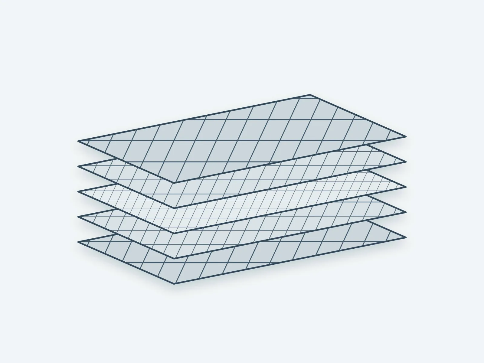
Sintered wire mesh: assign each layer a job
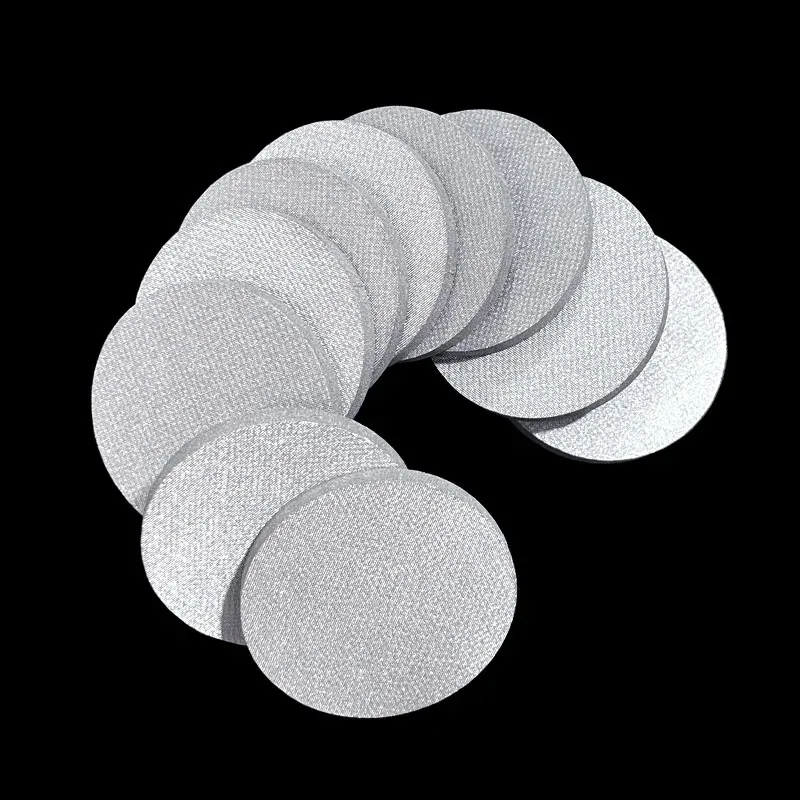
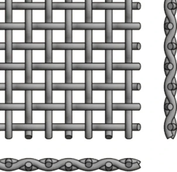
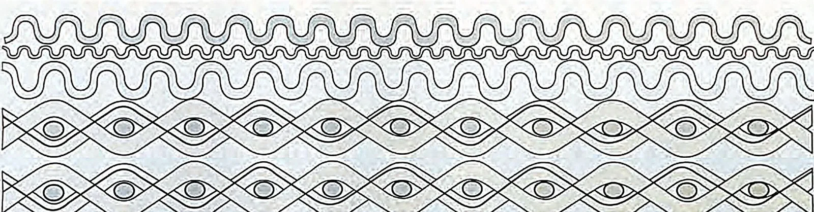
A five-layer construction combines a protective face, a filtration-control layer, a distribution layer and two support layers. Sintering locks the stack into a laminate that can be cut and formed into discs, tubes or cartridges. Other mesh laminates use different layer sequences or a perforated backing. Identify the control layer, upstream face, layer order and backing instead of treating every sintered mesh as one construction.
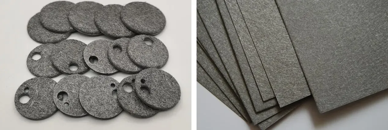
Fiber felt: a nonwoven filtering volume
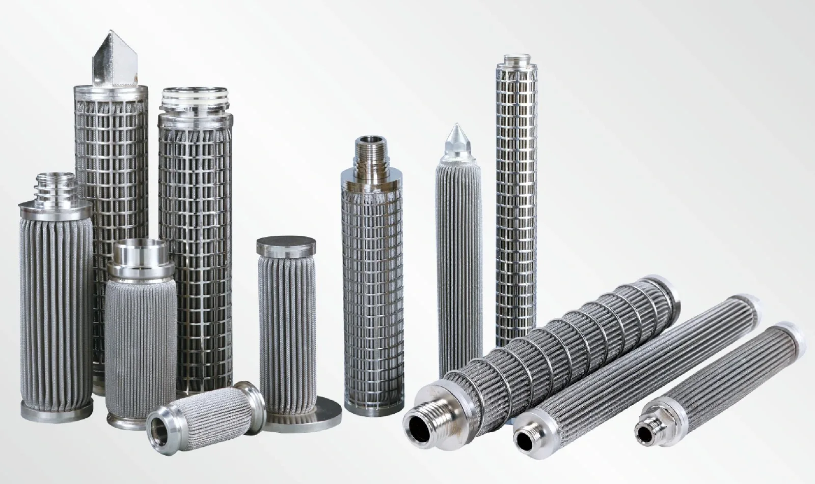
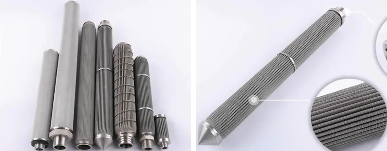
Fine metal fibers form a porous web with many interconnected passages. Sintering bonds the contacts; protective mesh can support one or both faces. The fiber network provides filtering volume for collected solids. Pleating develops more media area in a fixed envelope, while an inner core, outer restraint and drainage spaces maintain useful flow channels. Felt thickness and the thickness of a mesh-supported composite are separate dimensions.
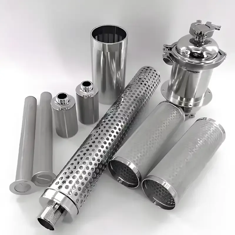
Powder: pore paths through a shaped porous body
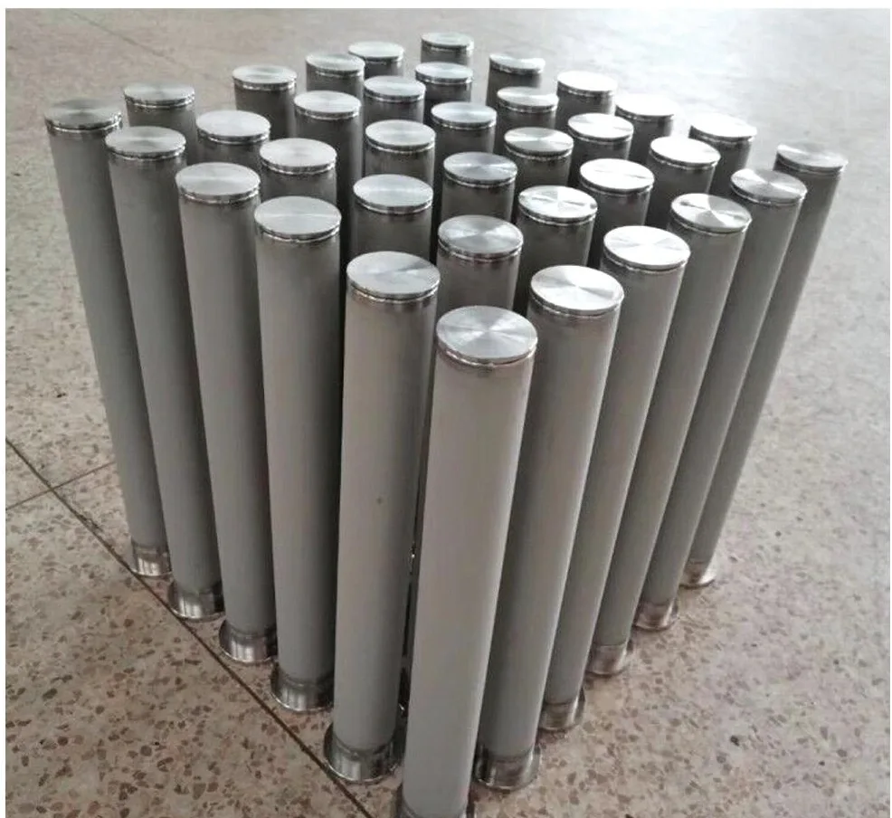
Selected powder is formed and sintered into porous discs, tubes, cups or other shapes. Particle selection, packing and wall thickness influence the connected passages and flow resistance. This route is useful for compact porous elements and gas-flow components. For a viscous liquid, examine pressure drop at the actual temperature and required flow before selecting the wall and active area.
Use a common test basis before ranking flow
A permeability value needs its fluid, differential pressure, temperature, exposed area and specimen thickness. Air flow at one differential pressure cannot be ranked directly against liquid flow or another test pressure. A bubble-point test uses a specified wetting liquid and procedure to examine the largest connected pore paths; retention testing uses a defined particle challenge. Keep both separate from a catalogue grade name and from structural pressure tests.
Cleaning recovery belongs to the complete element
Define the service flow direction and cleaning direction together with the support and welded joints. Reverse flow can load the laminate, pleats or porous wall differently. Select cleaning chemistry for all wetted metals and seals. Record clean pressure drop at fixed flow, fluid and temperature before use; repeat the same measurement after cleaning. Track recovery and pore-integrity checks over the intended service cycles rather than selecting solely from the first clean-flow result.
A component example for each route
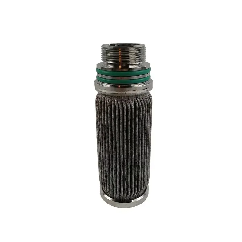
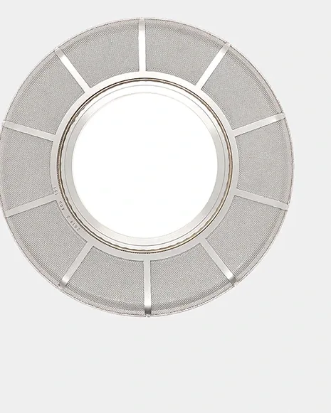
A flat filter disc can use a bonded mesh laminate with a defined sealing rim. A compact pleated cartridge can use mesh-supported fiber felt with drainage space and an inner core. A small gas element can use a shaped porous powder wall joined to a machined connection. Each drawing identifies the porous zone, solid joining zone and sealing boundary, so the housing interface remains part of the filtration design.
Select and validate the construction
1. Define the separation duty
Record fluid, viscosity at temperature, particle distribution, solids loading and target retention.
2. Choose the structural route
Select mesh laminate, felt or powder, then define area, thickness, support and joining zones.
3. Compare paired data
Use the same test medium and conditions; keep each value with its grade and specimen construction.
4. Plan the service cycle
Set cleaning direction and chemistry, then record clean-flow recovery and integrity for the finished element.
Carry the selected medium into a finished component
The same medium can be converted into different assemblies. A plain sintered-mesh disc is a supported sheet part; a metal leaf disc adds two filtering faces, internal drainage and a central collector. A powder tube combines a shaped porous body with a solid connection. These constructions have different installation drawings and replacement records.
Select the medium first, then define the active region, support, joining zone and sealing boundary for the finished form. Record media grade with its test method and geometry, while the housing interface receives its own dimensional checks. This keeps a sheet property, a porous-body designation and a complete-assembly test clearly identified.