
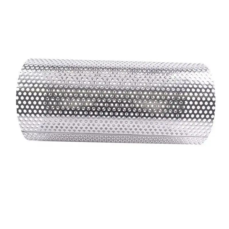
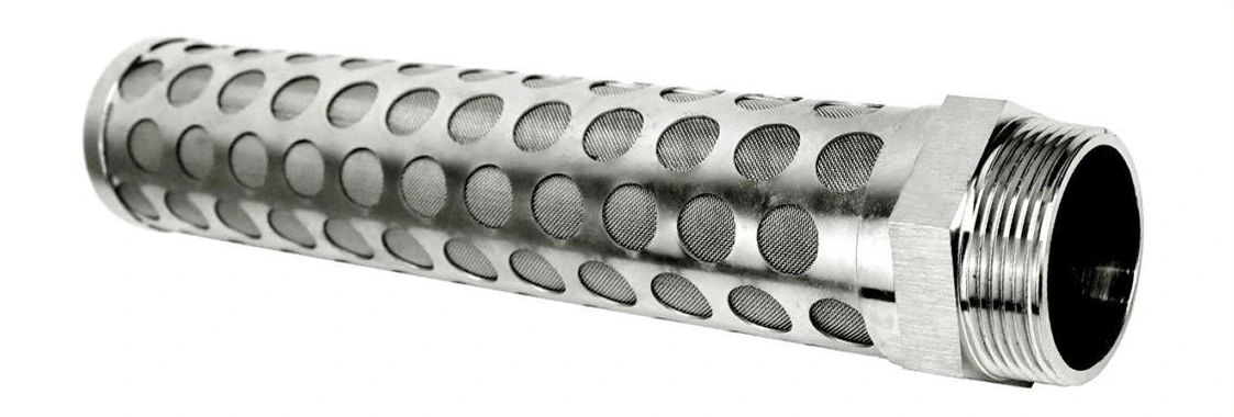
Construction and filtering function
A perforated core carries the filtering medium and provides fluid passages. Hole geometry, wall thickness, seam and end support define the structural load path.
A perforated filter support core is the load-bearing and drainage structure behind a flexible or pleated filtering medium. It keeps the media in position, transfers differential-pressure loads and provides a flow path to or from the clean side of the element.
Perforated metal screensShare a drawing, reference sample or application requirements to discuss the configuration.
Perforated filter support cores — Product view
A perforated core carries the filtering medium and provides fluid passages. Hole geometry, wall thickness, seam and end support define the structural load path.
Provide outside and inside diameters, length, wall thickness, end condition, roundness and mating-part tolerances. Define whether the core supports inward or outward pressure.
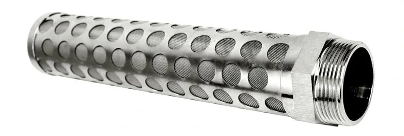
Review differential pressure, buckling risk, flow distribution and contact with fine media. Burrs and protruding joints can damage the filter layer, so surface and edge requirements belong on the drawing.
The inspection record identifies the material, finished dimensions, joining surfaces and sealing interfaces. Measurements follow the installed geometry and the stated test conditions.
The support core is specified from the filter layer outward: media-contact face, perforated wall, seam and end lands. Round holes and elongated openings are separate hole patterns; straight and spiral seams are separate joining layouts. Solid longitudinal margins provide a joining strip, and solid end bands connect the core to rings or end caps. For outside-in loading the core supports the filtering layer from inside; an outer support carries inside-out loading. Smooth media-contact surfaces and finished weld transitions protect the fine filtering layer during installation and cleaning.
| Component / interface | Defined function and inspection |
|---|---|
| Perforated wall | Hole shape, pitch, remaining ligament and wall thickness |
| Joining strip | Solid longitudinal margin and seam position |
| End bands | Unperforated lands for rings, welds and end caps |
| Media-contact face | Smooth edges and continuous support contact |
| Installed core | Roundness, end alignment and support direction |
| Dimension | Value (mm) |
|---|---|
| Outside diameter | 22–100 |
| Conventional tube wall thickness | 0.4–1.5 |
These dimensions apply to the conventional perforated support-tube series. The supporting wall carries the filter medium; perforation size is a drainage/support dimension and the separate filtering layer defines retention.
| Supply item | Order basis |
|---|---|
| Production lead time | 2–3 weeks after order and drawing confirmation. |
| Trial orders | Small trial quantities for fit and process evaluation. |
| Regular production orders | 50 pieces or US$3,000 per order. |
| Quotation basis | Material, finished dimensions, filter construction, connections and quantity. |
Examine a stainless steel perforated support tube with Ø3 mm through holes on a 5 mm, 60° staggered pattern. The Ø50 × 250 mm configuration has a 1 mm wall and solid end zones; rotate or section the core to see the flow openings and the support structure behind filter media.
Loading 3D model
| Parameter | Specification | Notes |
|---|---|---|
| Conventional tube wall thickness | 0.4–1.5 mm | These dimensions apply to the conventional perforated support-tube series. The supporting wall carries the filter medium; perforation size is a drainage/support dimension and the separate filtering layer defines retention. |
| Joining strip | Solid longitudinal margin and seam position | — |
| End bands | Unperforated lands for rings, welds and end caps | — |
| Media-contact face | Smooth edges and continuous support contact | — |
| Installed core | Roundness, end alignment and support direction | — |
| Component materials | 304 / 316L stainless steel; each filtering, support and end component has its own material designation. | — |
| Illustrated support-hole diameter | 3 mm | Geometry of the illustrated construction; finished dimensions follow the equipment interface drawing. |
| Displayed configuration | Ø3 on 5 pitch, 60° stagger mm | Ø3 mm holes at 5 mm pitch in a 60° staggered pattern give 32.6% geometric sheet open area. Solid seams and end bands are outside this calculation. |
| Illustrated geometry | Ø50 × 250 long × 1 wall mm | Geometry of the illustrated construction; finished dimensions follow the equipment interface drawing. |
| Illustrated unperforated end-band length | 15 each end mm | Geometry of the illustrated construction; finished dimensions follow the equipment interface drawing. |
| Outside diameter | 22–100 mm | These dimensions apply to the conventional perforated support-tube series. The supporting wall carries the filter medium; perforation size is a drainage/support dimension and the separate filtering layer defines retention. |
Delivered a Polish trial order combining fine 33 µm mesh with perforated support cylinders across three diameters; pre-shipment photographs were requested.
Delivered a Bulgarian food-equipment filter element with specified 0.8 mm perforations and approximately 2 mm of solid metal beside the weld line.
Internal support for pleated or cylindrical media, matched to the load direction.
Outer protection where handling or external contact could damage the filtering surface.
Perforated bodies used with a separately specified mesh liner.
Include these details when discussing your requirements.
View specificationsPerforated wall: Hole shape, pitch, remaining ligament and wall thickness; Joining strip: Solid longitudinal margin and seam position; End bands: Unperforated lands for rings, welds and end caps; Media-contact face: Smooth edges and continuous support contact; Installed core: Roundness, end alignment and support direction
The support core is specified from the filter layer outward: media-contact face, perforated wall, seam and end lands. Round holes and elongated openings are separate hole patterns; straight and spiral seams are separate joining layouts. Solid longitudinal margins provide a joining strip, and solid end bands connect the core to rings or end caps. For outside-in loading the core supports the filtering layer from inside; an outer support carries inside-out loading. Smooth media-contact surfaces and finished weld transitions protect the fine filtering layer during installation and cleaning.
The inspection record identifies the material, finished dimensions, joining surfaces and sealing interfaces. Measurements follow the installed geometry and the stated test conditions.
Explore related products and technical guidance.
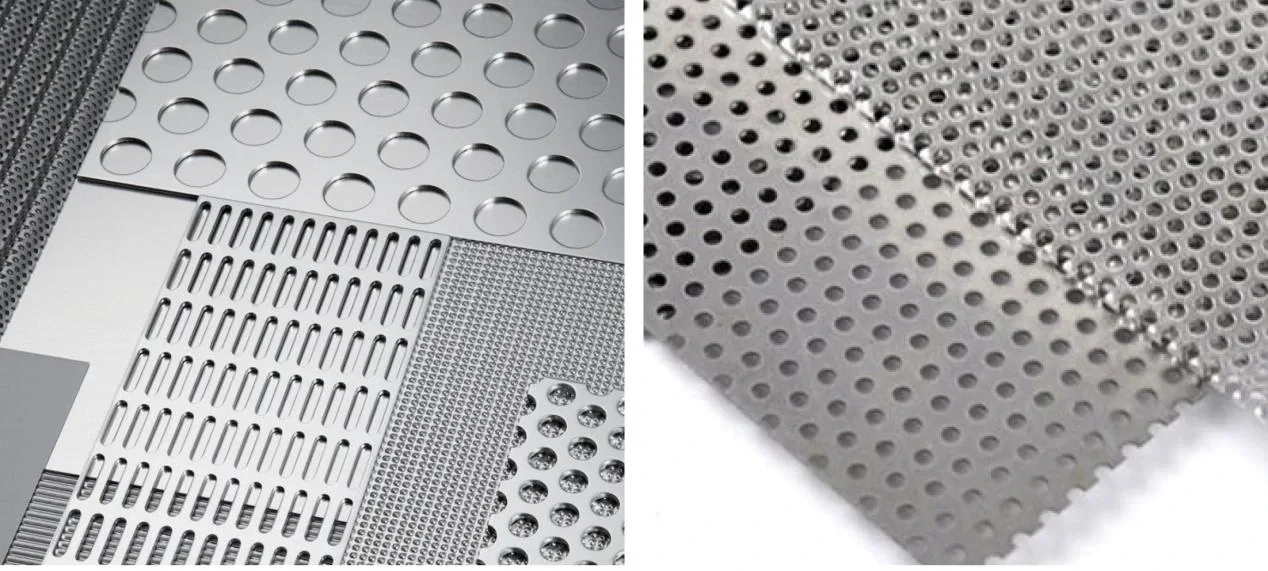
Perforated screen panels use a patterned metal plate where stiffness and repeatable geometric openings are required.
View details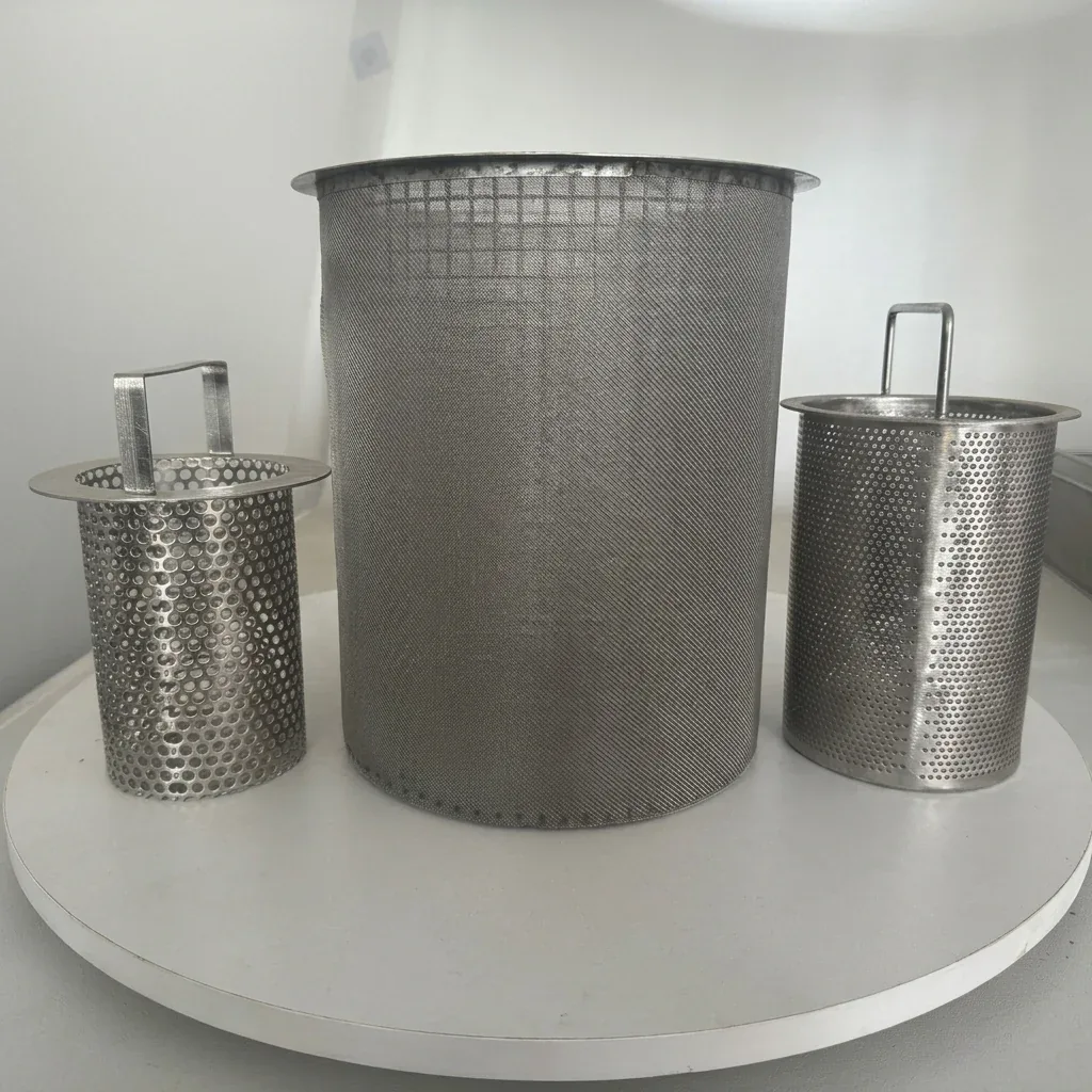
Removable stainless steel baskets combine a perforated shell, closed bottom, seating rim and lifting handle.
View details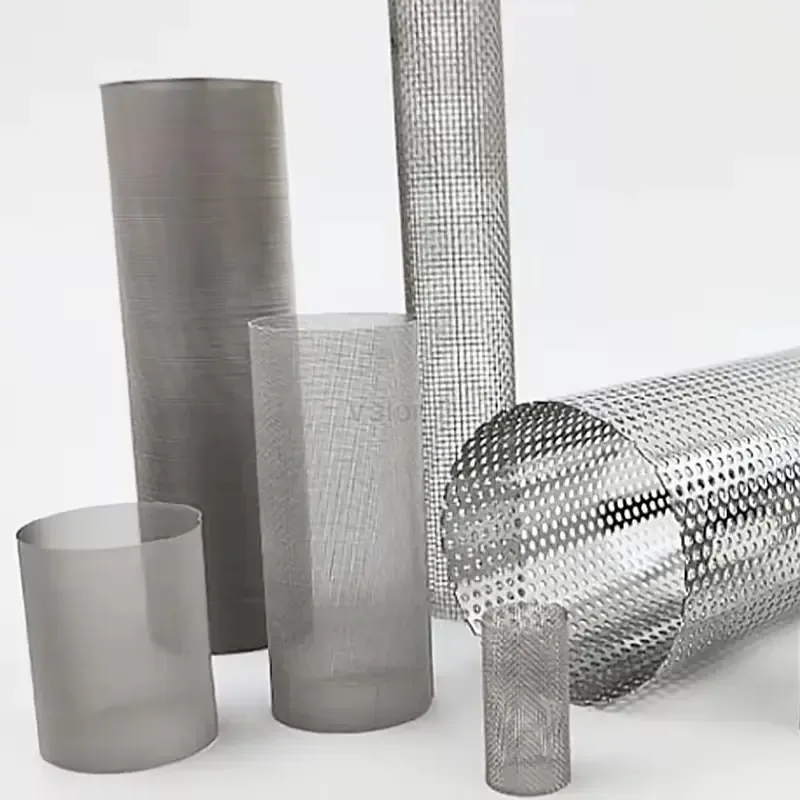
Stainless steel woven mesh cylinders combine a defined wire-cloth opening with a welded cylindrical body, reinforced ends and flow-directed support.
View details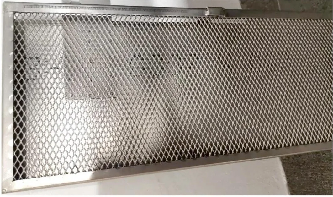
Slit-and-stretched metal sheets with integral diamond openings for filter backing, drainage and formed support parts.
View detailsDefine the dimensions, media, joints and inspection records before confirming the order.