
Shijiazhuang, Hebei, Chinasales@kaifil.com
KAIFIL
Cone strainers

Temporary cone strainers

Pointed start-up strainers with perforated shells and mesh liners. Cone geometry, flange rings, flow direction and commissioning inspection in one technical guide.

Perforated metal screens
Cone envelope
Base diameter, axial length, included angle and tip clearance
Filter stack
Perforated support, woven liner, layer order and inlet face
Flange joint
Ring diameter, bore, thickness, gasket land and tab
Commissioning
Flow, fluid, debris, pressure-drop monitoring and removal access

Share a drawing, reference sample or application requirements to discuss the configuration.

Product details

Geometry, support and flow direction

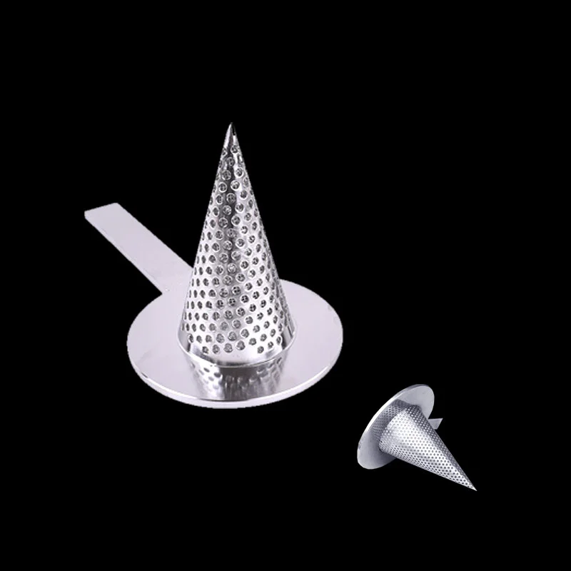
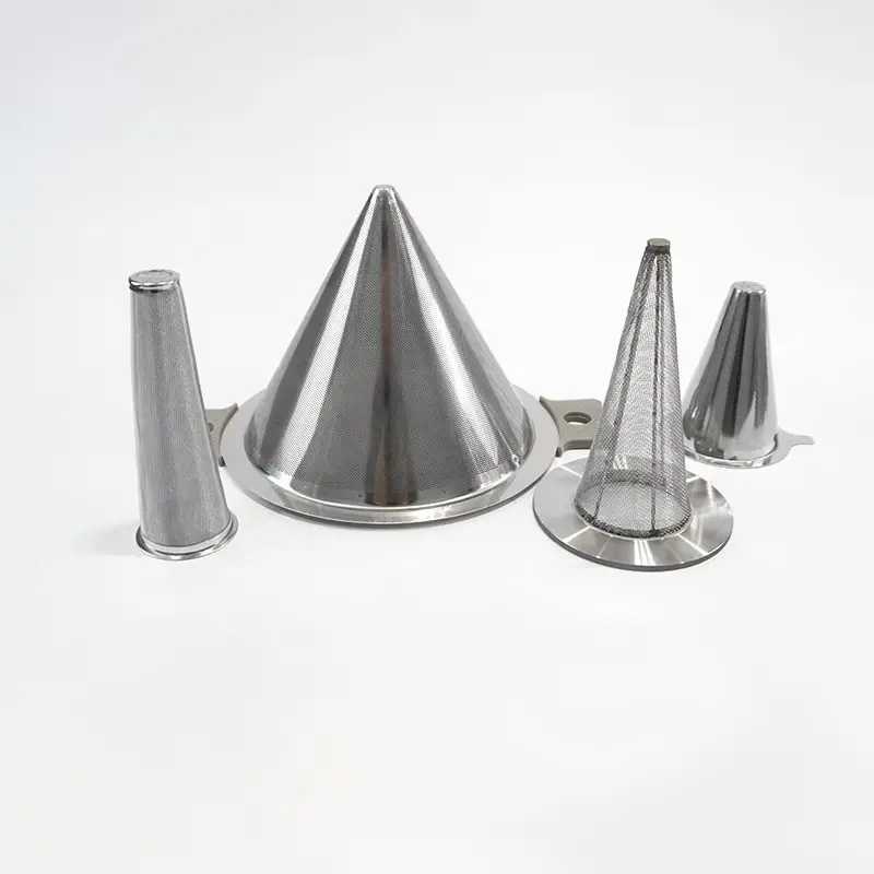
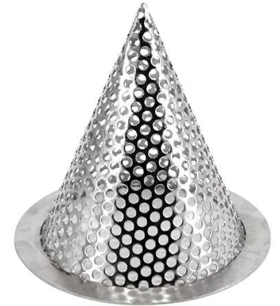
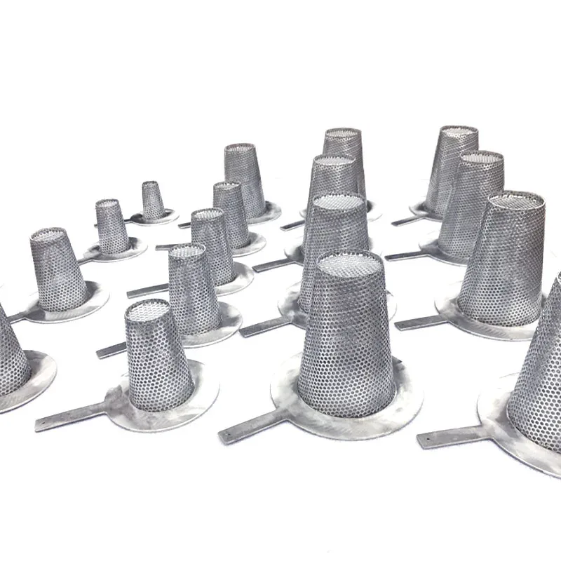
The pointed cone uses its sloping wall to provide screening area within the pipe spool. Base diameter, axial insertion length and cone angle define the envelope together. A perforated shell supports a finer woven liner; the liner’s opening and attachment are specified separately. The flow arrow identifies the inlet face and the support side, linking mesh placement to the differential-pressure load path.
Flange installation and commissioning

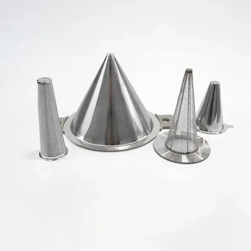
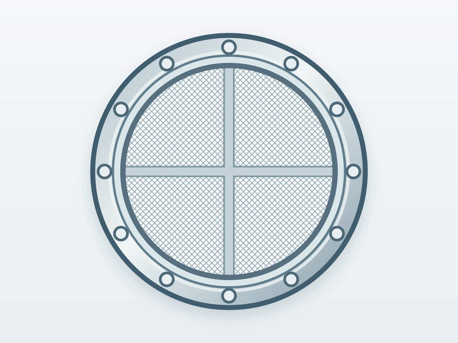
The mounting ring is clamped between the named pipe flanges. Ring outside diameter, bore, thickness and gasket land define the joint; an identification tab remains accessible after assembly. The spool drawing includes cone-tip clearance and removal access. Commissioning records clean pressure drop, accumulated debris and differential pressure during flushing; inspection checks the cone seam, ring flatness and liner attachment before reassembly.

Temporary cone strainers — Product view

Witch’s hat strainers for pipeline commissioning

The term witch’s hat strainer identifies the pointed-cone form of a temporary start-up strainer installed between pipeline flanges. For procurement, record pipe size and flange facing together with cone length, support-ring geometry, free space in the removable pipe spool, perforation and any fine-mesh overlay. The flow arrow determines the feed face: the mesh is backed by the perforated cone on the discharge side. Specify gasket seating, handle access and the commissioning plan for inspection and removal. These inputs define the complete conical insert and its installation fit.

Start-up strainer installation schedule

Start-up strainer installation schedule

FeatureDrawing and operating definition
Cone envelopeBase diameter, axial length, included angle and tip clearance
Filter stackPerforated support, woven liner, layer order and inlet face
Flange jointRing diameter, bore, thickness, gasket land and tab
CommissioningFlow, fluid, debris, pressure-drop monitoring and removal access
Temporary cone strainers — Perforated support openings

Temporary cone strainers — Perforated support openings

Hole diameter (in)Hole diameter (mm)
1/161.5875
1/83.175
1/46.35
1/212.7

Round support-hole sizes are stated in inches with exact millimetre conversions using 1 in = 25.4 mm. Hole pitch, sheet thickness and solid mounting lands complete the support geometry. The optional woven liner has its own mesh and wire specification.

Temporary cone strainers — Woven liner specifications

Temporary cone strainers — Woven liner specifications

Mesh count / inchWire diameter (mm)Clear aperture (mm)
200.4060.86
400.2540.38
800.1400.18
1000.1020.15

Choose the woven liner by its mesh, wire and clear aperture. The perforated support and the finer filtering cloth have separate openings; support holes provide backing and drainage, while the cloth controls the selected particle opening.

Ordering and production

Ordering and production

Supply itemOrder basis
Production lead time2–3 weeks after order and drawing confirmation.
Trial ordersSmall trial quantities for fit and process evaluation.
Regular production orders50 pieces or US$3,000 per order.
Quotation basisMaterial, finished dimensions, filter construction, connections and quantity.

Specifications

Temporary cone strainers
ParameterSpecificationNotes
Cone envelopeBase diameter, axial length, included angle and tip clearance—
Filter stackPerforated support, woven liner, layer order and inlet face—
Flange jointRing diameter, bore, thickness, gasket land and tab—
CommissioningFlow, fluid, debris, pressure-drop monitoring and removal access—
Material304 / 316L stainless steel—
Perforated support openings1/16 / 1/8 / 1/4 / 1/2 inRound support-hole sizes are stated in inches with exact millimetre conversions using 1 in = 25.4 mm. Hole pitch, sheet thickness and solid mounting lands complete the support geometry. The optional woven liner has its own mesh and wire specification.
Illustrated geometryDN100 line; cone length 150 mmGeometry of the illustrated construction; finished dimensions follow the equipment interface drawing.
Mesh-liner geometry shown20 mesh; wire Ø0.25; clear opening 1.02 mmFor square weave:25.4/20−0.25=1.02 mm.

Applications

Pipeline commissioning

The screen captures construction debris during flushing and is removed after commissioning.

Pump protection during flushing

The upstream screen intercepts debris before it reaches the pump inlet.

Frequently asked questions

How is the installed envelope defined?

The mounting ring is clamped between the named pipe flanges. Ring outside diameter, bore, thickness and gasket land define the joint; an identification tab remains accessible after assembly. The spool drawing includes cone-tip clearance and removal access. Commissioning records clean pressure drop, accumulated debris and differential pressure during flushing; inspection checks the cone seam, ring flatness and liner attachment before reassembly.

How are support and flow direction specified?

The pointed cone uses its sloping wall to provide screening area within the pipe spool. Base diameter, axial insertion length and cone angle define the envelope together. A perforated shell supports a finer woven liner; the liner’s opening and attachment are specified separately. The flow arrow identifies the inlet face and the support side, linking mesh placement to the differential-pressure load path.
Technical enquiry

Define the dimensions, media, joints and inspection records before confirming the order.

Technical details (optional)
Selection inputs

WhatsApp

Search