Shijiazhuang, Hebei, Chinasales@kaifil.com
KAIFIL
Filter parts and accessories

Filter Locating Rings

KAIFIL manufactures machined stainless steel locating rings for metal filter inserts, holders and end assemblies. Plain, stepped and flanged profiles establish the radial position, seating height and repeatable fit of the filter within its mating component.

Profile options
Plain / stepped / flanged
Material
304 / 316L
Locating functions
Radial centering / axial seating / spacing
Manufacturing route
Turning / boring / facing; drilled or milled features

Share a drawing, reference sample or application requirements to discuss the configuration.

Product details

Position the filter from defined mating surfaces

A locating ring establishes where the filter sits inside a holder or end assembly. The pilot diameter controls radial alignment, while the shoulder or axial face sets the installation height. Defining these functions separately makes the ring easier to specify and helps preserve filter alignment when the assembly is opened and rebuilt.

Plain, stepped and flanged configurations

Plain rings provide a controlled bore and outside diameter in a compact section. Stepped rings add a pilot and shoulder for simultaneous centering and axial seating. Flanged rings add a wider face for attachment holes or contact with the holder. The geometry follows the mating parts, with lead-in chamfers and edge relief where needed for assembly.

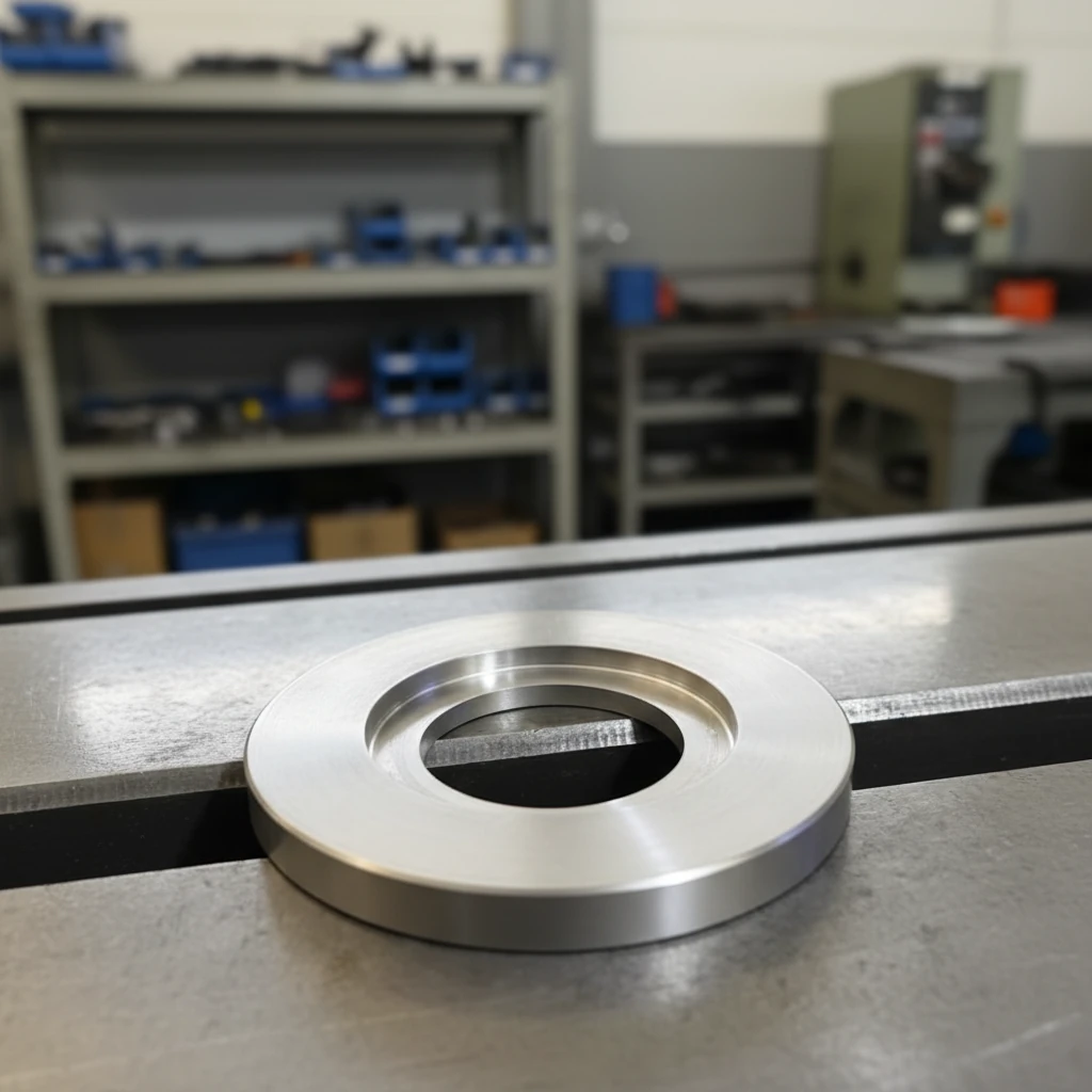
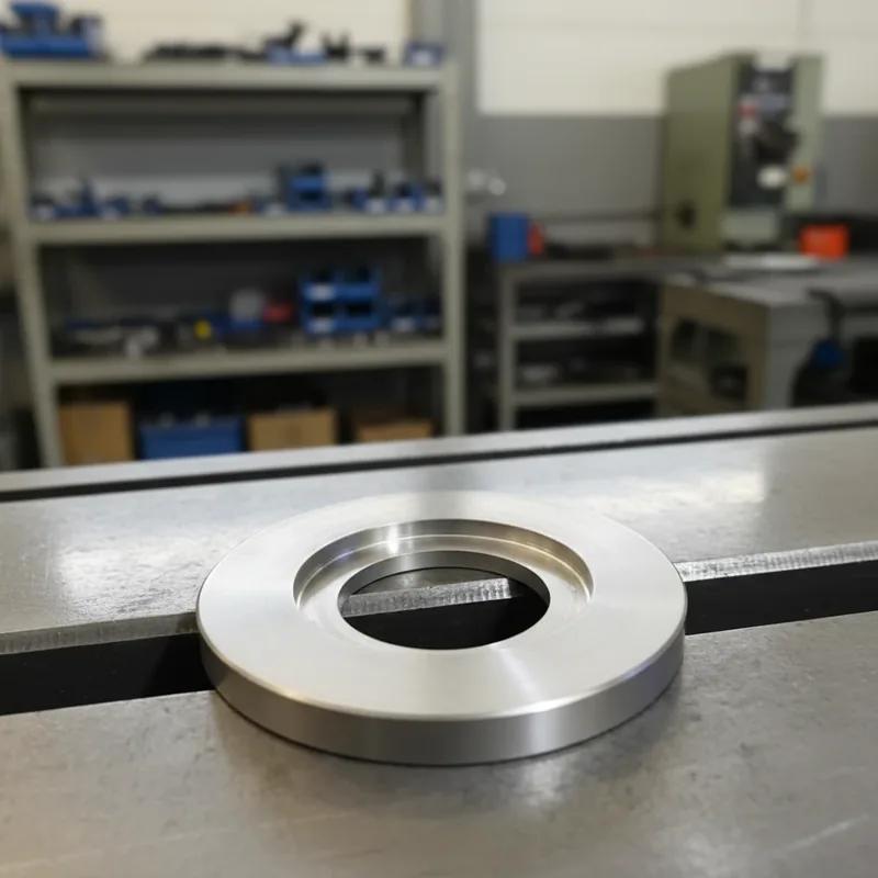
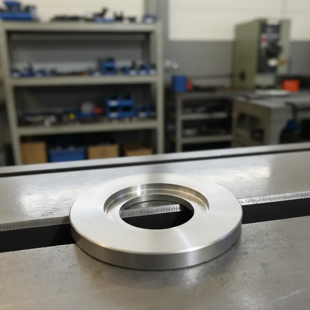
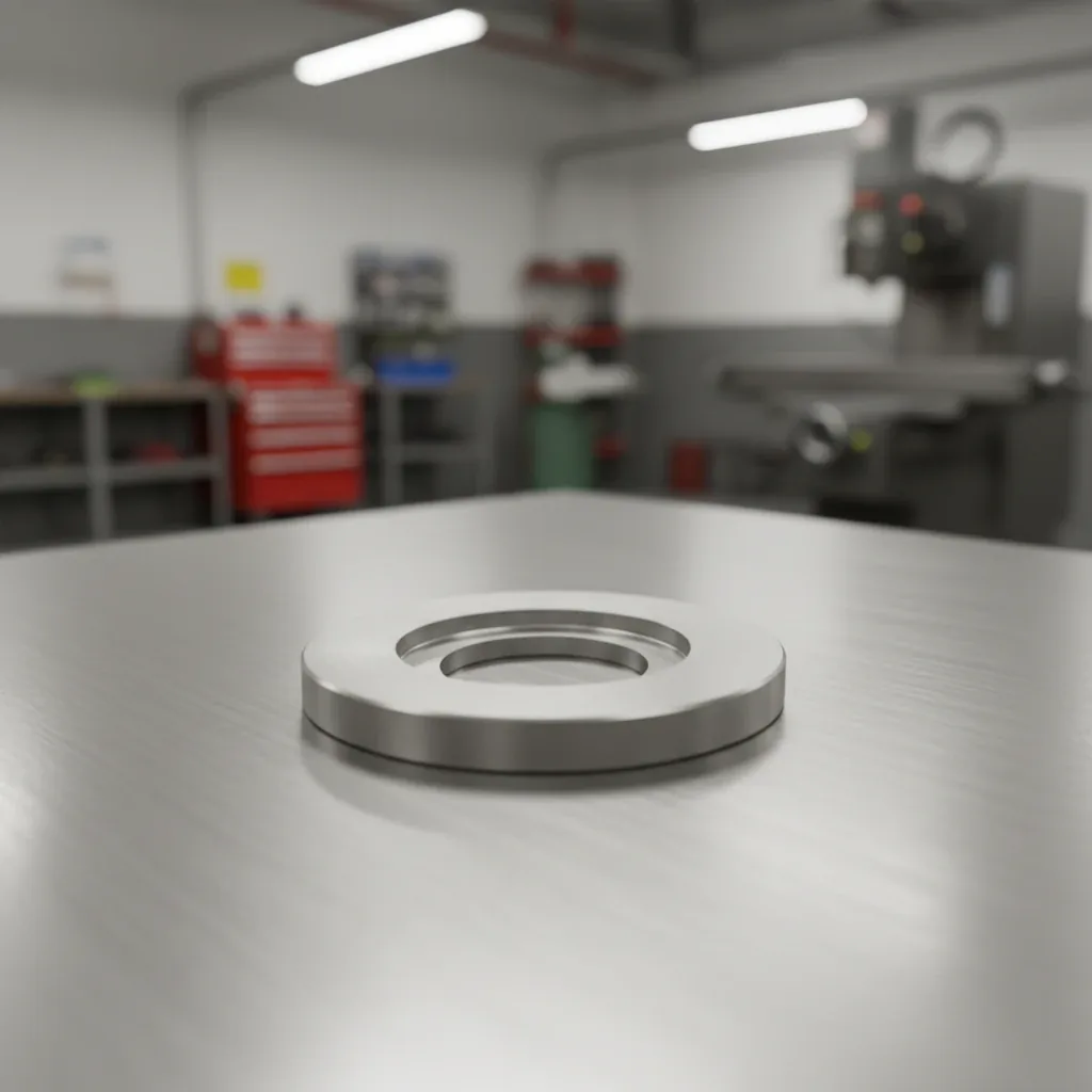
Locating-ring bore and flat seating face

Bores, pilots and datum faces

We define the primary locating diameter and its reference face first. The remaining bore, shoulder, hole pattern and groove are dimensioned from those datums. A close outside fit is useful only if the bore and seating face remain correctly related to it. For thin rings, the drawing also identifies the measurement condition so clamping does not disguise distortion.

Machining and surface details

Turning and boring create the circular locating surfaces and axial shoulders. Milling or drilling adds mounting holes, reliefs and anti-rotation features. Contact edges are deburred, and surfaces can be specified as machined, polished or passivated. Seal-contact faces and grooves receive their own surface requirements when the ring also carries a gasket or O-ring.

Fit for removal and thermal movement

A removable filter normally needs a defined clearance fit so it can be seated and withdrawn without damage. Temperature changes, material pairing and residue in the joint can alter removal force. Set pilot clearance, shoulder height and the complete tolerance stack together; an unnecessarily tight ring can make maintenance difficult without improving filtration.

Coordinate positioning, sealing and filtration

The locating ring positions the component; a specified seal closes the joint; the mesh or sintered medium performs filtration. We can coordinate these parts in a filter-holder assembly while retaining separate dimensions for each function. A filter screen can be retained at the bore when the drawing includes its seat and fixing method.

Integration with the filter assembly

The locating ring belongs between the filter element and its holder. In a disc holder, its bore surrounds the disc seat while its pilot locates the holder assembly. In a cylindrical insert, the shoulder sets the installed axial position. The bill of materials lists ring, filter medium, gasket or O-ring and retaining hardware separately. Assembly inspection checks the locating diameter and seated height first, then verifies seal contact and an unobstructed flow opening.

Specify the clamp interface and the locating features separately

For a filter holder connected with an inch-size clamp fitting, identify the nominal connection together with the ferrule flange outside diameter d6 and the flow bore d1. The 1 in and 1½ in connections both have a 50.5 mm flange, while their bores are 22.1 and 34.8 mm respectively. Recording both dimensions identifies the intended flow opening and seal interface when the connection is assembled.

The locating ring is machined to its own holder drawing in 304 or 316L stainless steel. Specify its outside diameter, bore, pilot diameter, shoulder height and axial seating face from the holder datums. A ring that also retains a filter disc has a defined disc seat and retention feature; the gasket contact profile and compression belong to the seal detail. This separates the connection size, the ring’s centering fit and the active filter opening in the same assembly.

Assembly interface map

Assembly interface map

Component / interfaceDefined function and inspection
Filter disc seatSupports the disc perimeter and defines its retaining diameter
Locating pilotCenters the ring relative to the holder datum
Axial shoulderSets element position and stack height
Seal groove or faceCarries the separate O-ring or gasket
RetainerHolds the stack without covering the active filter area
Inch-size clamp connections: mating ferrule dimensions

Inch-size clamp connections: mating ferrule dimensions

Nominal connection (in)Ferrule flange OD d6 (mm)Flow bore d1 (mm)
150.522.1
1½50.534.8
26447.5
2½77.560.2
39172.9
411997.4
Ordering and production

Ordering and production

Supply itemOrder basis
Production lead time2–3 weeks after order and drawing confirmation.
Trial ordersSmall trial quantities for fit and process evaluation.
Regular production orders50 pieces or US$3,000 per order.
Quotation basisMaterial, finished dimensions, section geometry, mating interface and quantity.

Specifications

Filter Locating Rings
ParameterSpecificationNotes
Profile optionsPlain / stepped / flangedSelect the locating and seating features from the mating assembly.
Material304 / 316LMatch contact media and adjacent metal parts.
Locating functionsRadial centering / axial seating / spacingIdentify which diameter and face perform each function.
Manufacturing routeTurning / boring / facing; drilled or milled featuresCircular datum features are coordinated in the machining plan.
Main dimensionsOD × bore × overall heightAdd shoulder diameter and step height for stepped parts.
Pilot fitDefined clearance / specified transition fitRemovable assemblies need installation and extraction clearance.
Datum systemLocating diameter + axial reference faceDimension the bore, shoulder and mounting pattern from the same datums.
Geometry controlsRunout / perpendicularity / flatness / coaxial relationshipUse the drawing control appropriate to each mating feature.
Mounting detailsBolt holes / counterbores / notches / anti-rotation featuresSet locations relative to the locating datum.
Edge conditionDeburred edges / lead-in chamfers / corner reliefsPreserve the width of functional locating lands.
Seal interfaceSeparate gasket face or O-ring grooveSpecify seal material, groove and compression separately.
Supply formatLoose ring / matched filter-holder assemblyScreen, seal and hardware can be identified as separate assembly items.
Mating inch-size clamp connections1 / 1½ / 2 / 2½ / 3 / 4 inThe table identifies the mating ferrule flange and flow bore. Ring OD, pilot, bore and height are dimensioned on the filter-holder drawing.

Materials: 304 and 316L stainless steel. Material is coordinated with the filter, holder and wet-contact surfaces.

Product details

Examine the part profile, contact faces and construction details.

Locating-ring bore and flat seating face

Locating-ring bore and flat seating face

Locating-ring bore and flat seating face

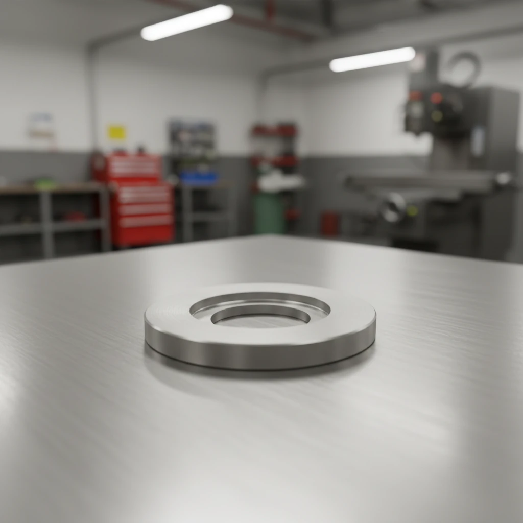
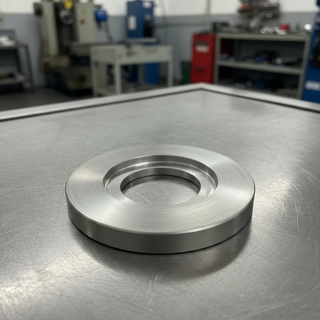
Low-angle view of a machined locating ring

Low-angle view of a machined locating ring

Low-angle view of a machined locating ring

Selection guide

Include these details when discussing your requirements.

Name the locating surfaces
Mark the pilot diameter and axial stop face rather than applying the same tolerance to every surface.
Select the profile
Use a plain ring for spacing, a stepped ring for centering and seating, or a flange when mounting features need a wider face.
Control the complete stack
Include filter length, ring height, seal thickness and holder depth when setting the installed position.
Plan removal clearance
Choose the fit for operating temperature, material pair and maintenance access.
Keep sealing dimensions distinct
A locating shoulder is not automatically a sealing face. Dimension a gasket land or O-ring groove explicitly.

Frequently asked questions

How is a locating ring different from a support ring?

A locating ring primarily controls position through its bore, pilot and datum face. A support ring primarily transfers load and reinforces the filter structure. One part can combine the functions when the drawing defines both.

Can the ring include an O-ring groove?

Yes. The groove is defined with its own width, depth, diameter and surface condition, alongside the locating dimensions. The O-ring compound and cross section are selected separately.

Do you offer a universal locating-ring size?

The ring is made around the mating filter and holder. Provide the bore, pilot, height and shoulder dimensions so the part fits the assembly directly.

How are tolerances specified?

Assign the required fit to the locating diameter and use geometric controls for the related bore and face. This gives functional surfaces the necessary accuracy without making every non-contact surface equally tight.

Can a screen be fitted inside the ring?

Yes. A holder assembly can include a wire-mesh or sintered-mesh disc, with its seating diameter and retention method defined separately from the ring’s external fit.

Is a tighter fit always better?

No. A removable filter needs enough clearance for assembly, temperature changes and cleaning deposits. Select a fit that maintains alignment while allowing the intended maintenance procedure.

Technical enquiry

Define the dimensions, media, joints and inspection records before confirming the order.

Technical details (optional)
Selection inputs

WhatsApp

Search