Treat the connection as three linked functions
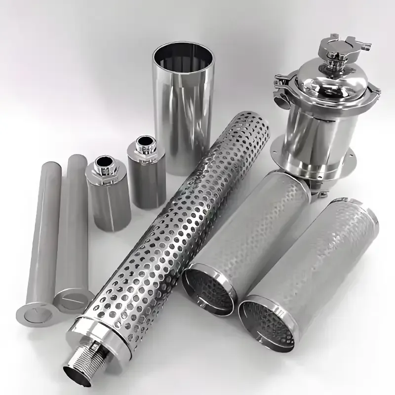
An end connection locates the element, separates the clean and dirty sides, and transfers assembly and operating loads. These functions may use different surfaces. A locating ring can center a cartridge while a separate gasket provides the seal. Draw the filter end together with its mating seat so every contact has a defined role.
DOE and SOE describe the end arrangement
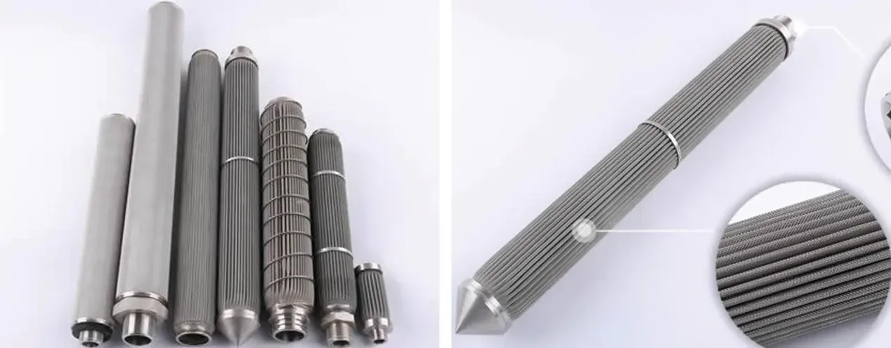
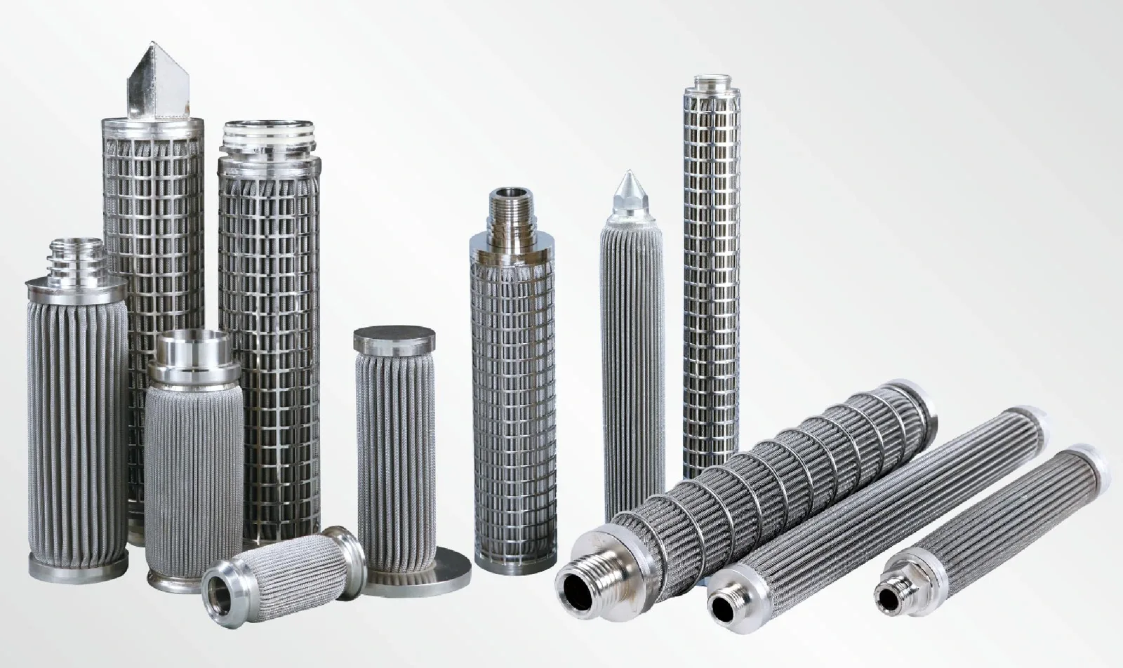
DOE means double open end: both ends are open, commonly with axial gaskets compressed between the element and housing seats. SOE means single open end: one end is closed and the open end connects to the matching housing seat. The assembly drawing defines the service flow direction. The closed end can include a locating or retaining feature. State the total length, compressed sealing stack and closure arrangement; these determine how the element is seated.
222 and 226: record the actual spigot and seal engagement
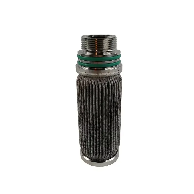
222 and 226 identify common cartridge connection families. A push-in spigot uses O-rings against the mating bore; locating or retaining features distinguish particular end designs. For a 226 end with locking lugs, show their position and engagement with the housing. Provide spigot diameters, groove sections, insertion depth, lead-in and the mating bore. The code is an identification field; the interface drawing supplies the dimensions and tolerances.
Threads and flanges need a defined sealing face
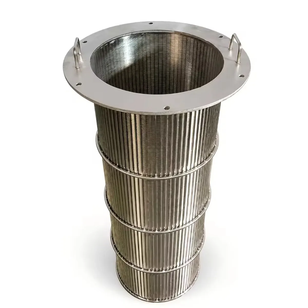
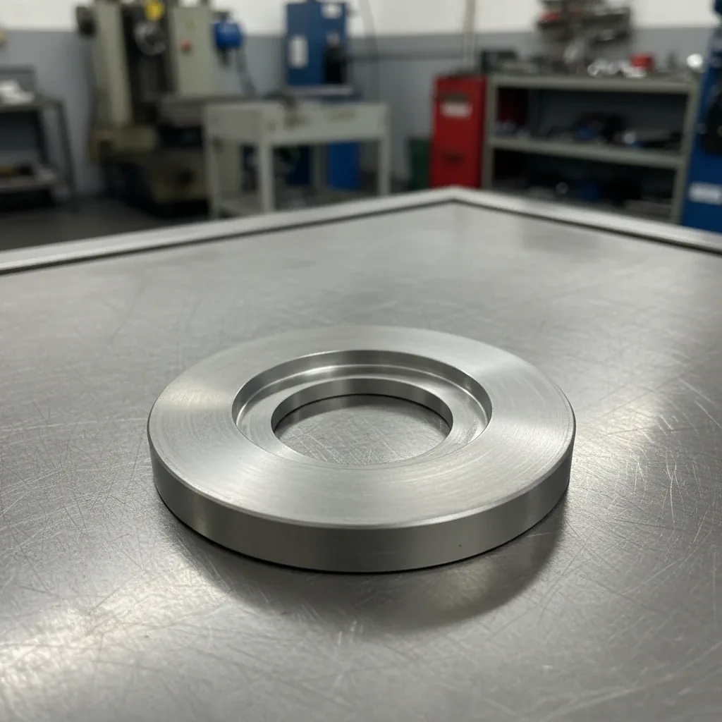
For a threaded end, specify thread form, size, pitch, engagement and the point where sealing occurs. A shoulder gasket or radial O-ring seals at its designed surface; an intended thread seal needs its own sealing method. For a flange, record face geometry, gasket seat, bolt arrangement and alignment. Keep a removable cartridge flange distinct from a pressure-vessel or pipe flange designation.
Match the seal to its groove and exposure
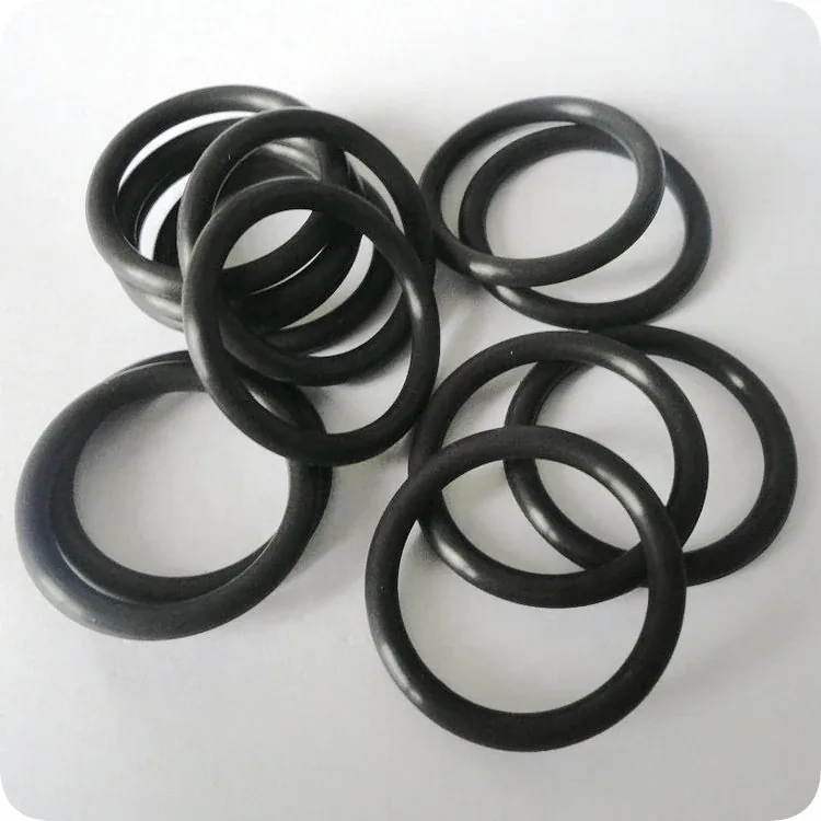
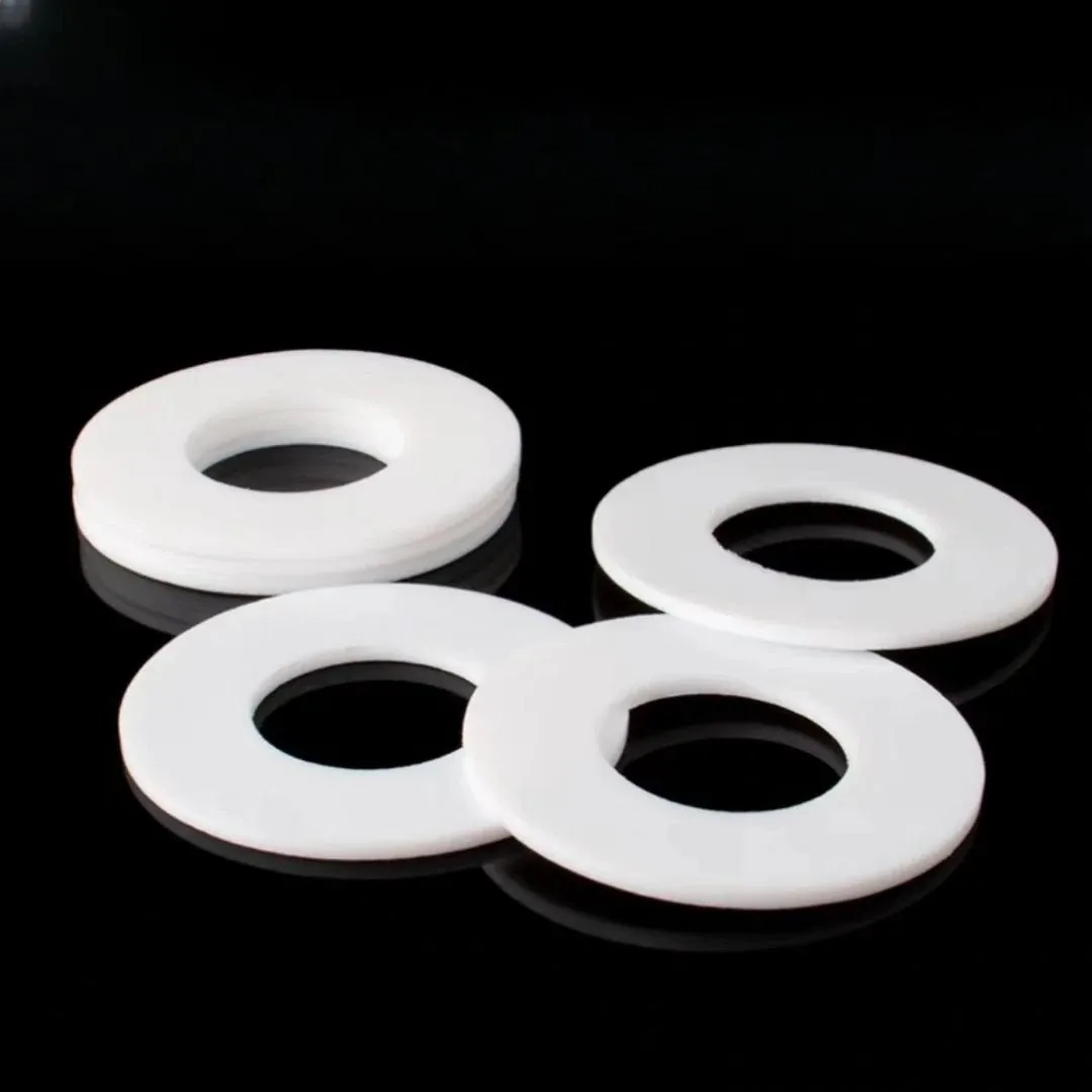
A radial O-ring seals between the spigot and bore; an axial gasket or face O-ring seals between opposed faces. Record O-ring free-state inside diameter and cross section, compound, hardness and position. Groove depth, width, clearance and lead-in control seating. Select the exact seal compound for process fluid, cleaning chemicals and temperature cycle, including installation lubricant. The metal alloy and the seal compound are separate order fields.
Inspect fit, bypass and load as separate questions
Dimensional inspection checks concentricity, sealing surfaces, groove edges and insertion or clamping depth. An assembly bypass or leak test checks the sealing boundary under its defined conditions. A pore-integrity test checks the porous medium and its joints. A structural differential-pressure test loads the element in a stated direction with the intended support. A connection code alone supplies none of these acceptance results.
A replacement example: keep the housing seat in the drawing
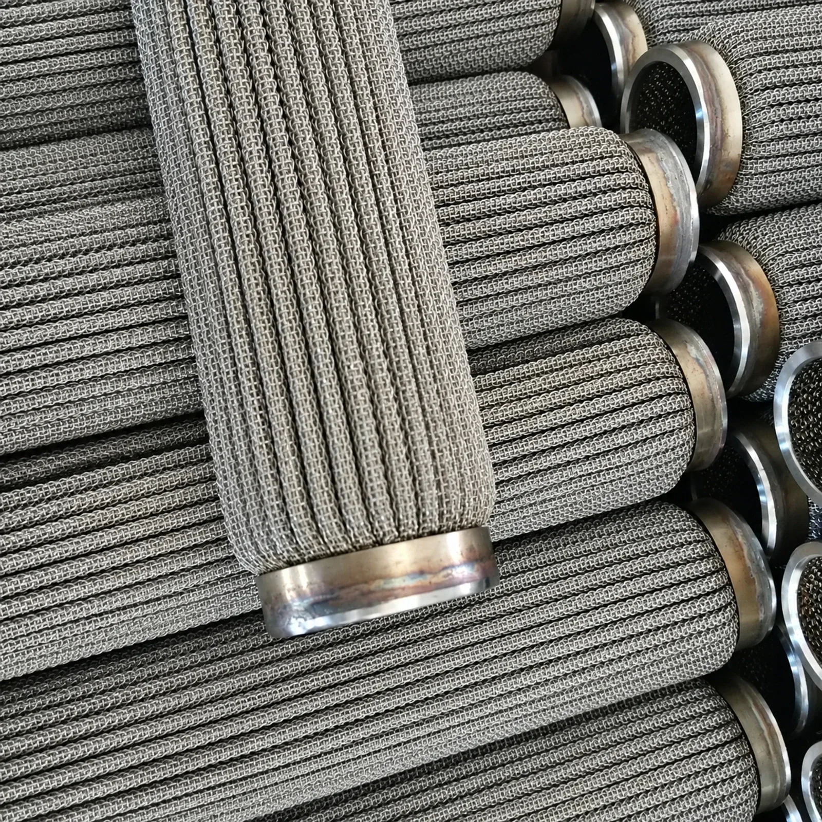
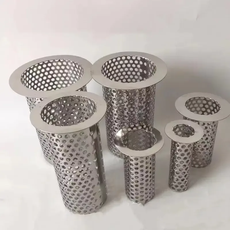
When replacing a pleated metal element, measure the housing bore or gasket seat as well as the old cartridge. Record the closed-end locator, available insertion space and removal clearance. Compare the porous length separately from the overall assembly length. A worn or swollen service seal helps identify the position, while an unused seal or groove drawing defines the replacement size.
Prepare the interface in four steps
1. Identify the installed arrangement
Record DOE or SOE, end code if present, open/closed ends and flow direction.
2. Measure both mating parts
Show element and housing datums, sealing surfaces, grooves, engagement and assembly clearances.
3. Specify the seal set
Give size, compound, hardness, quantity and position for every O-ring or gasket.
4. Agree assembly and acceptance
Define insertion or clamping procedure, clean handling and separate fit, seal, integrity and structural checks.