
Shijiazhuang, Hebei, Chinasales@kaifil.com
KAIFIL
Screen packs

Kidney-shaped screen packs

Non-round woven packs for screen-changer pockets. Kidney radii, indexing features, layer sequences, retained borders and installed stack dimensions.

Metal wire mesh
Profile
Inner and outer radii, chord, end arcs and indexing features
Retained border
Seating width, locating holes, spot-weld positions or rim
Layer sequence
20 /40 /20 or 40 /80 /200 /80 /40 mesh; individual wire diameters
Installed stack
Compressed thickness, active area and support-plate contact

Share a drawing, reference sample or application requirements to discuss the configuration.

Product details

Construction and function

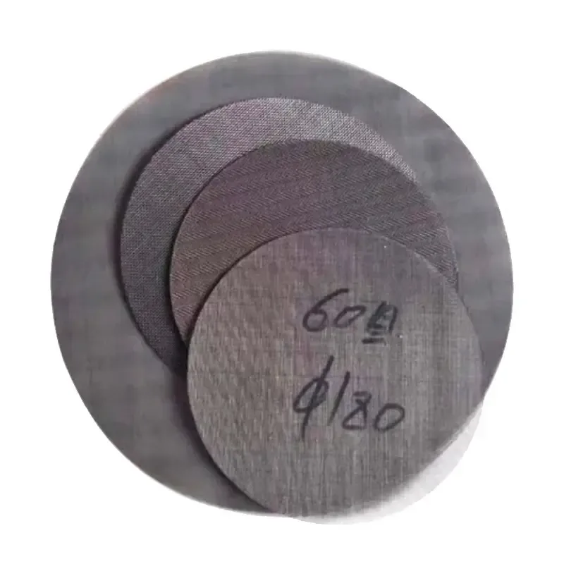
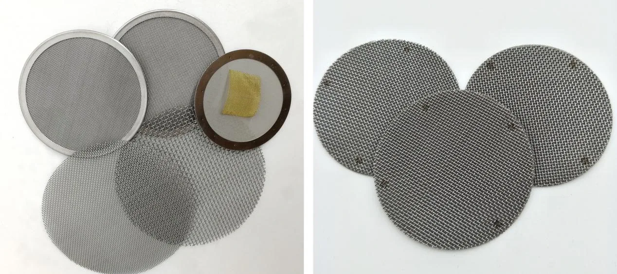
A kidney-shaped pack follows the curved, non-round pocket of a screen changer. Every layer is cut to the same registered outline so the active opening and clamped border coincide. Inner and outer radii, chord length, end arcs and indexing features describe the profile. Loose layers, localized spot welds and a perimeter rim are distinct retention constructions.
Installation and inspection

The flat profile is checked against the changer drawing or a dedicated template. The drawing defines locating holes, contact edge, compressed thickness and the clearance to the moving carrier. Weld points sit in the retained border and the support plate carries the downstream load. Inspection verifies outline, layer sequence, flatness, edge retention and indexing clearance. The machine schedule records polymer, melt temperature, throughput and change-out differential pressure.

Use the asymmetric outline as the installation datum

A kidney-shaped pack is located by its curved outline and the matching changer pocket. Put the long and short spans, curved boundaries and locating features on one profile drawing. Mark which face enters the pocket and which direction receives the melt, so the asymmetric pack cannot be specified from one nominal diameter.

Specify layer order and finished thickness with the profile. The holder defines the clamped strip around the outline and the exposed filtering region inside it. Keep joining points and any edge treatment with that boundary. Inspect the finished pack against the same profile datum used for the equipment pocket.

Component and interface schedule

Component and interface schedule

FeatureTechnical definition
ProfileInner and outer radii, chord, end arcs and indexing features
Retained borderSeating width, locating holes, spot-weld positions or rim
Layer sequence20 /40 /20 or 40 /80 /200 /80 /40 mesh; individual wire diameters
Installed stackCompressed thickness, active area and support-plate contact
Illustrated geometryIllustrated geometry: 120 × 80 mm
Moving interfaceCarrier clearance, orientation marks and change-out position
Use the asymmetric outline as the installation datum

Use the asymmetric outline as the installation datum

Controlled featureInstallation taskCheck on the finished part
Asymmetric outlineLocates in the matching recessLong/short spans and curved profile
Face and flow directionOrients the pack in the changerInstalled face and inlet-to-outlet marks
Layer schedulePositions filter and backing layersWeave, wire, layer order and thickness
Clamped boundarySeparates retention from active regionPocket contact and exposed screen outline
Kidney-shaped screen packs — Inlet-to-outlet mesh sequence

Kidney-shaped screen packs — Inlet-to-outlet mesh sequence

Inlet-to-outlet mesh sequenceControlling mesh / inchWire diameter (mm)Clear aperture (mm)
20 / 40 / 20400.2540.38
40 / 80 / 200 / 80 / 402000.05330.0737

Mesh sequences run from inlet to outlet. The table specifies the controlling square-weave layer; every protective and backing layer retains its own wire diameter. The rim and changer pocket determine finished pack dimensions.

Ordering and production

Ordering and production

Supply itemOrder basis
Production lead time2–3 weeks after order and drawing confirmation.
Trial ordersSmall trial quantities for fit and process evaluation.
Regular production orders50 pieces or US$3,000 per order.
Quotation basisMaterial, finished dimensions, filter construction, connections and quantity.

Specifications

Kidney-shaped screen packs
ParameterSpecificationNotes
ProfileInner and outer radii, chord, end arcs and indexing features—
Retained borderSeating width, locating holes, spot-weld positions or rim—
Layer sequence20 /40 /20 or 40 /80 /200 /80 /40 mesh; individual wire diameters—
Installed stackCompressed thickness, active area and support-plate contact—
Illustrated geometryMaximum envelope 120 ×80 mm; detailed radii defined on profile drawingGeometry of the illustrated construction; finished dimensions follow the equipment interface drawing.
Moving interfaceCarrier clearance, orientation marks and change-out position—
Material304 / 316L stainless steel—

Production details and documented projects

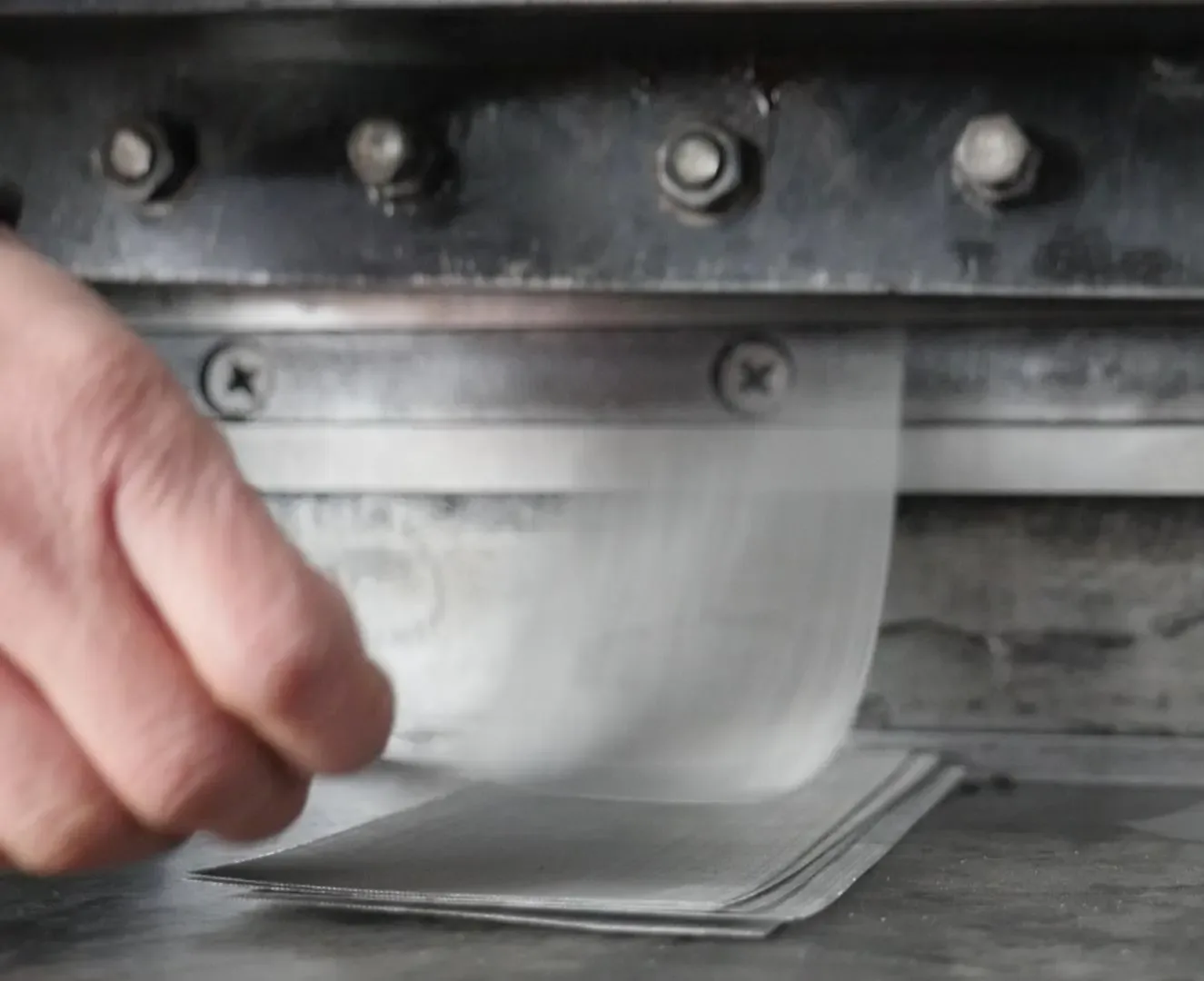
Mesh blank cutting
Mesh blank cutting

Mesh blank cutting

The wire-cloth layers are cut from a measured sector or kidney outline and joined where the changer clamps them. The pack can be loose, spot-welded or rimmed according to the cavity.

Applications

Rotary screen changers

The indexed kidney outline follows the moving carrier pocket.

Non-round melt filtration

Matched layers provide one registered active area within the clamped border.

Frequently asked questions

What defines the installed assembly?

The flat profile is checked against the changer drawing or a dedicated template. The drawing defines locating holes, contact edge, compressed thickness and the clearance to the moving carrier. Weld points sit in the retained border and the support plate carries the downstream load. Inspection verifies outline, layer sequence, flatness, edge retention and indexing clearance. The machine schedule records polymer, melt temperature, throughput and change-out differential pressure.

How do the media and support work together?

A kidney-shaped pack follows the curved, non-round pocket of a screen changer. Every layer is cut to the same registered outline so the active opening and clamped border coincide. Inner and outer radii, chord length, end arcs and indexing features describe the profile. Loose layers, localized spot welds and a perimeter rim are distinct retention constructions.
Screen edge and layer-stack checklist

Complete the component fields and return the sheet with the assembly drawing and order reference.

Download: Screen edge and layer-stack checklist

Editable CSV with component dimensions, construction and inspection fields.

Technical enquiry

Define the dimensions, media, joints and inspection records before confirming the order.

Technical details (optional)
Selection inputs

WhatsApp

Search