
Shijiazhuang, Hebei, Chinasales@kaifil.com
KAIFIL
Screen packs

Rimmed extruder screen packs

Rimmed woven screen packs for melt filtration. Compare 20/40/20 and 40/80/200/80/40 stacks, rim geometry, breaker-plate support and inspection.

Metal wire mesh
Three-layer stack
20 /40 /20 mesh; each layer has its own wire diameter
Five-layer stack
40 /80 /200 /80 /40 mesh; separate construction
Illustrated pack diameter
3.661 in
Rim and fit
Rim material, width, thickness, pocket diameter and seating depth

Share a drawing, reference sample or application requirements to discuss the configuration.

Product details

Construction and function

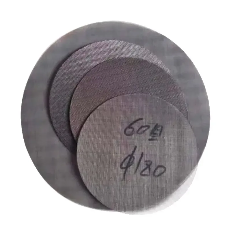
A rimmed extruder pack captures a defined sequence of woven screens inside one metal edge. The finer layer performs melt filtration and the coarser layers support and protect it. The layer list runs from inlet to outlet and identifies weave, mesh count and wire diameter for every layer. A crimped rim mechanically encloses the edges; a welded rim uses defined joint locations outside the active opening.
Installation and inspection

The pack seats in the breaker-plate pocket. Outside diameter, compressed stack thickness, rim width and seating depth define the fit; the downstream breaker plate carries the load transmitted through the stack. The operating schedule records polymer, melt temperature, throughput and screen-change differential pressure. Inspection checks layer identity and order, perimeter retention, thickness, flatness and the absence of loose wire ends.

Fit the retained stack to the changer pocket

The rim turns the selected layers into one handled insert. Its outside edge fits the changer recess, while its section occupies part of the available closure height. Specify the compressed layer stack and rim profile together so the assembly seats on the intended land without loading the active cloth at the edge.

Mark inlet and outlet faces, then list every filtering and backing layer in that order. Position the support against the breaker plate and define the exposed opening. Keep that layer schedule with each batch label; after removal, inspect the rim closure and the loading pattern before specifying the next pack.

Component and interface schedule

Component and interface schedule

FeatureTechnical definition
Three-layer stack20 /40 /20 mesh; each layer has its own wire diameter
Five-layer stack40 /80 /200 /80 /40 mesh; separate construction
Illustrated pack diameterIllustrated geometry: 3.661 in for the 20 /40 /20 pack construction
Rim and fitRim material, width, thickness, pocket diameter and seating depth
Flow and supportInlet-to-outlet sequence and downstream breaker-plate support
Process inputsPolymer, melt temperature, throughput and change-out differential pressure
Fit the retained stack to the changer pocket

Fit the retained stack to the changer pocket

Controlled featureInstallation taskCheck on the finished part
Rim outside contourFits the changer pocketDiameter or outline and seating clearance
Finished stack heightFits the closure spaceRim section and compressed layers
Inlet-to-outlet orderPlaces filtering and backing layersLayer identity and support-side orientation
Active windowExposes the required screen areaRim coverage and breaker-plate support
Fit the retained stack to the changer pocket
Rimmed extruder screen packs — Inlet-to-outlet mesh sequence

Rimmed extruder screen packs — Inlet-to-outlet mesh sequence

Inlet-to-outlet mesh sequenceControlling mesh / inchWire diameter (mm)Clear aperture (mm)
20 / 40 / 20400.2540.38
40 / 80 / 200 / 80 / 402000.05330.0737

Mesh sequences run from inlet to outlet. The table specifies the controlling square-weave layer; every protective and backing layer retains its own wire diameter. The rim and changer pocket determine finished pack dimensions.

Ordering and production

Ordering and production

Supply itemOrder basis
Production lead time2–3 weeks after order and drawing confirmation.
Trial ordersSmall trial quantities for fit and process evaluation.
Regular production orders50 pieces or US$3,000 per order.
Quotation basisMaterial, finished dimensions, filter construction, connections and quantity.

Specifications

Rimmed extruder screen packs
ParameterSpecificationNotes
Three-layer stack20 /40 /20 mesh; each layer has its own wire diameter—
Five-layer stack40 /80 /200 /80 /40 mesh; separate construction—
Illustrated pack diameter3.661 inGeometry of the illustrated construction; finished dimensions follow the equipment interface drawing.
Rim and fitRim material, width, thickness, pocket diameter and seating depth—
Flow and supportInlet-to-outlet sequence and downstream breaker-plate support—
Process inputsPolymer, melt temperature, throughput and change-out differential pressure—
Material304 / 316L stainless steel—

Selection guide

Include these details when discussing your requirements.

View specifications
Single-pack diameter
3.661 in for the 20 /40 /20 pack construction

Production details and documented projects

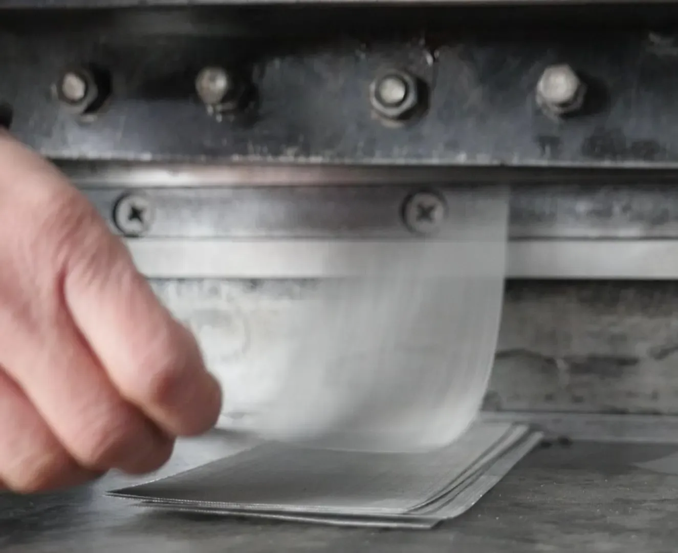
Mesh blank cutting
Mesh blank cutting

Mesh blank cutting

Coarse support and fine control layers are cut to the cavity profile, then captured by a metal perimeter. A 20/40/20 mesh stack is one documented example, not a universal retention rating.

Applications

Polymer extrusion

The pack retains solid contamination in the melt before flow reaches downstream tooling.

Recycling melt filtration

A defined mesh sequence and screen-change differential pressure organize the filtration cycle.

Frequently asked questions

What defines the installed assembly?

The pack seats in the breaker-plate pocket. Outside diameter, compressed stack thickness, rim width and seating depth define the fit; the downstream breaker plate carries the load transmitted through the stack. The operating schedule records polymer, melt temperature, throughput and screen-change differential pressure. Inspection checks layer identity and order, perimeter retention, thickness, flatness and the absence of loose wire ends.

How do the media and support work together?

A rimmed extruder pack captures a defined sequence of woven screens inside one metal edge. The finer layer performs melt filtration and the coarser layers support and protect it. The layer list runs from inlet to outlet and identifies weave, mesh count and wire diameter for every layer. A crimped rim mechanically encloses the edges; a welded rim uses defined joint locations outside the active opening.
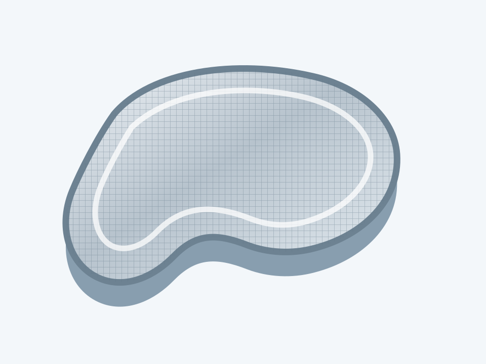
Screen edge and layer-stack checklist

Complete the component fields and return the sheet with the assembly drawing and order reference.

Download: Screen edge and layer-stack checklist

Editable CSV with component dimensions, construction and inspection fields.

Technical enquiry

Define the dimensions, media, joints and inspection records before confirming the order.

Technical details (optional)
Selection inputs

WhatsApp

Search