Product forms
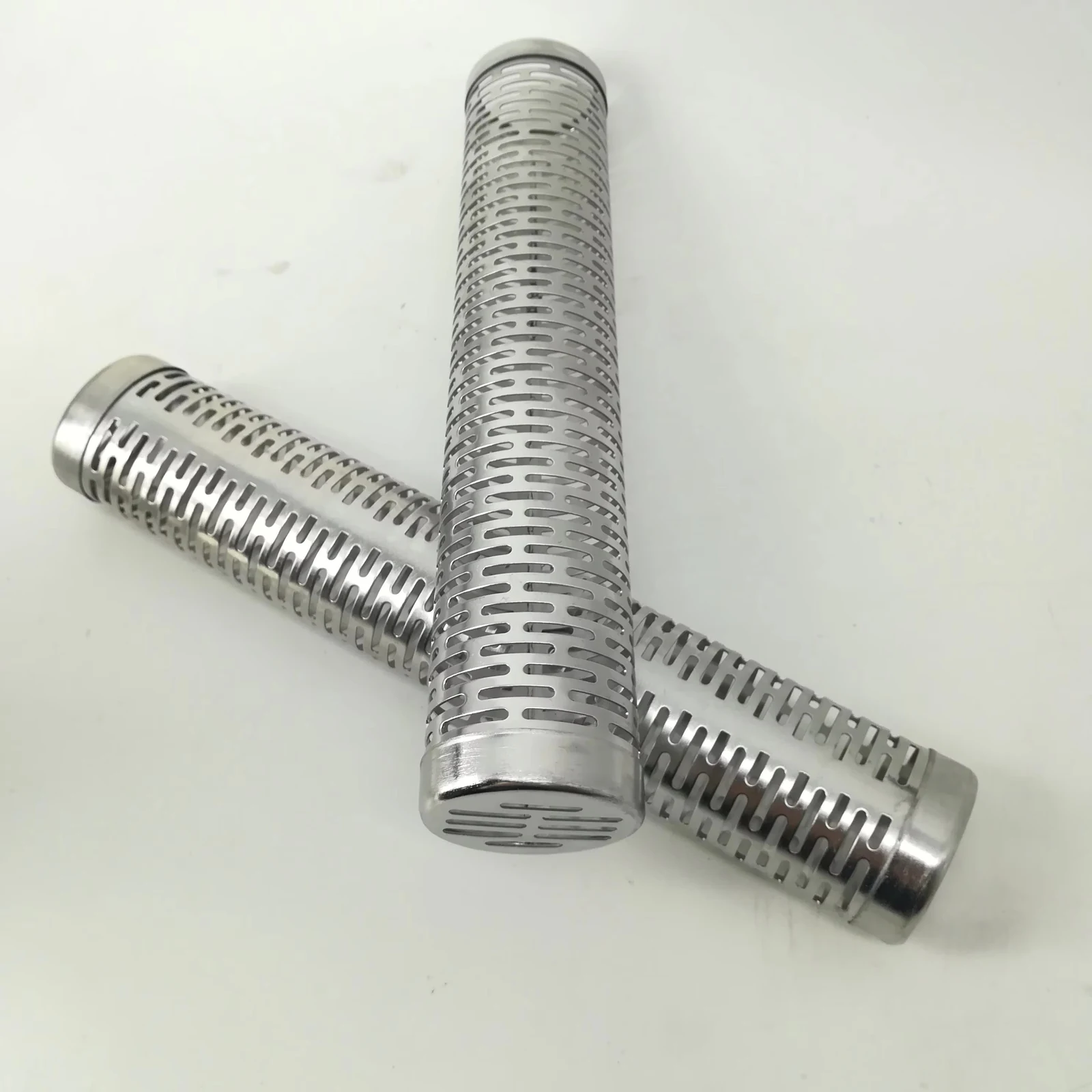
Kaifil manufactures laser-slotted filter tubes with axial, circumferential, staggered or zoned patterns. Solid end bands provide mounting, welding and sealing surfaces for tubular screens and filter-media supports.
Kaifil manufactures laser-slotted filter tubes with axial, circumferential, staggered or zoned patterns. Solid end bands provide mounting, welding and sealing surfaces for tubular screens and filter-media supports.
Laser-perforated and slotted screensShare a drawing, reference sample or application requirements to discuss the configuration.
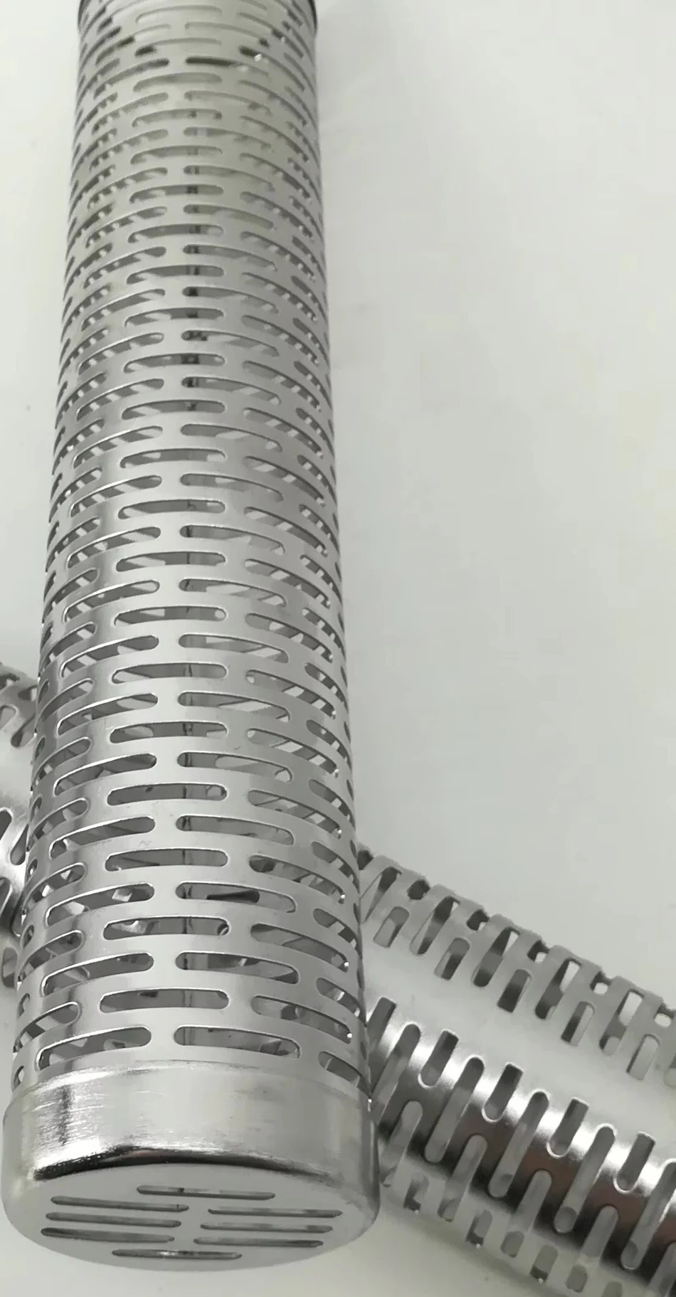
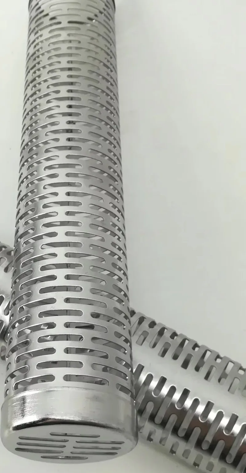
Three metal filter tubes showing different elongated slot patterns and finished ends.
Kaifil manufactures laser-slotted filter tubes with axial, circumferential, staggered or zoned patterns. Solid end bands provide mounting, welding and sealing surfaces for tubular screens and filter-media supports.
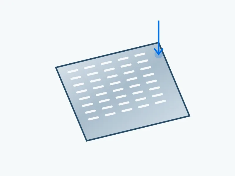
The tube geometry defines outside diameter D, wall thickness t, clear slot width w and overall slot length L as separate dimensions. The working face fixes where the narrow opening is measured. Axial and circumferential pitches define the remaining metal in their respective directions; solid end bands define the connection and sealing zones.
The slot-layout calculation uses a tube geometry of Ø50 mm outside diameter × 1.5 mm wall × 300 mm length, with 0.5 × 10 mm slots. An axial centre pitch of 12 mm and overall slot length of 10 mm leave a 2 mm axial bridge: 12−10=2 mm. This table defines the calculation geometry; the finished component drawing separately defines its mounting and sealing dimensions.
304, 316L and special alloys are available with plain, ringed, threaded or flanged ends. We finish and inspect the slot edges, working-face width, pitch, roundness and connection dimensions for the specified flow and installation.
The slot schedule separates slot width, slot length, row pitch and the remaining metal bridges. Axial and circumferential patterns describe the slot direction on the tube, while stagger and zoned layouts describe row arrangement. The drawing identifies the working face and the unslotted end bands. Laser-cut slots, punched bridge slots and wedge-wire gaps are different constructions: this page specifies slots cut through a tube wall. Inspect the narrow opening and its edges, remaining bridges, roundness and clear assembly access.
| Component / interface | Defined function and inspection |
|---|---|
| Slot width | Narrow opening measured at the working face |
| Slot length and pitch | Set axial open length and remaining bridge |
| Circumferential spacing | Defines metal between adjacent rows |
| Unslotted end band | Provides material for the specified end joint |
| Assembly role | Tubular screen or support behind a separate finer medium |
| Parameter | Calculation value | Unit | Definition |
|---|---|---|---|
| Tube outside diameter D | 50 | mm | Tube envelope used in this calculation. |
| Tube-wall thickness t | 1.5 | mm | Wall used in this calculation. |
| Tube length | 300 | mm | Length used in this calculation. |
| Slot width w × overall length L | 0.5 × 10 | mm | The length includes both end contours. |
| Axial centre pitch p | 12 | mm | Pitch between consecutive slot centres. |
| Calculated axial bridge b | 2 | mm | b=p−L=12−10; bridge along the slot row. |
| Supply item | Order basis |
|---|---|
| Production lead time | 2–3 weeks after order and drawing confirmation. |
| Trial orders | Small trial quantities for fit and process evaluation. |
| Regular production orders | 50 pieces or US$3,000 per order. |
| Quotation basis | Material, finished dimensions, filter construction, connections and quantity. |
| Parameter | Specification | Notes |
|---|---|---|
| Tube construction | Seamless or formed-and-joined tube | — |
| Tube outside diameter D | D mm | Outside diameter, defined separately from the slot dimensions. |
| Tube-wall thickness t | t mm | Wall dimension normal to the tube surface. |
| Clear slot width w | w mm | Narrow clear opening at the specified working face. |
| Overall slot length L | L mm | End-to-end slot length, including the end contours. |
| Slot layout | Axial · circumferential · staggered · zoned | State slot direction on the tube, longitudinal and circumferential pitch, minimum bridge, edge distance and active length. |
| Tube geometry for the slot-layout calculation | Ø50 × t1.5 × 300; w0.5 × L10 mm | Calculation inputs: D50 × wall1.5 × length300; slot w0.5 × L10 mm. These dimensions define this layout calculation. |
| Solid end zones | To installation drawing | Keep uncut space for end rings, welds, threads, flanges and seals. Exclude these zones from clear-area calculations. |
| Material options | 304 / 316L stainless steel; project alloys | Specify fluid, temperature, cleaning chemistry and material documentation. |
| Connection options | Plain · ringed · threaded · flanged | — |
| Inspection basis | Finished dimensions, cut edges, roundness and interface inspection | Check slot width and pitch, cut-edge condition, remaining metal, roundness, end fit and cleanliness. |
Materials: 304 / 316L · Special alloys
A slotted tube fits a cylindrical seat while retaining a solid clamping band. Define particle size, flow direction and removal clearance.
Zoned slots can release or collect fluid along a tube. Row count, pitch and open area are set with pressure loss and available support.
Wider slots can support a separate woven or sintered layer. In this construction, the finer layer sets filtration performance; the slotted tube supplies strength and flow access.
Custom replacement cartridges reproduce the housing dimensions, sealing faces and end connections.
Include these details when discussing your requirements.
Give slot length and axial pitch separately. A 10 mm slot at 12 mm axial pitch leaves a 2 mm axial bridge. Circumferential pitch and the stagger pattern define the remaining metal between adjacent rows.
Specify the clear slot width at the working face, together with slot length and wall thickness. Slot length increases open area; width sets the narrow geometric passage for the selected flow orientation.
Explore related products and technical guidance.
Define the dimensions, media, joints and inspection records before confirming the order.