
Shijiazhuang, Hebei, Chinasales@kaifil.com
KAIFIL
Filter panels and framed screens

Laser-slotted screen panels

Laser-slotted metal panels with defined width, length, rounded or rectangular ends, open-area calculations, solid borders, supports and edge inspection.

Laser-perforated and slotted screens
Construction
Laser-cut metal plate
Slot geometry used in the calculation
w0.5 × L10 mm
Material options
304 / 316L stainless steel
Installed dimensions
Panel mounting and finished edges

Share a drawing, reference sample or application requirements to discuss the configuration.

Product details

Programmed slots in a continuous metal panel

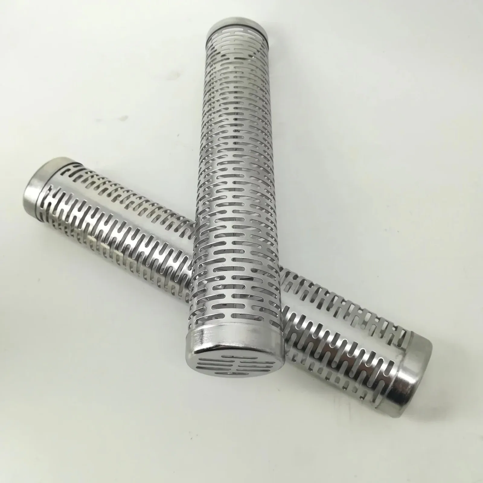
Laser cutting forms elongated passages directly in the sheet. The drawing identifies each slot zone, its orientation and its solid bridges. A slot is specified by clear width, total length, end shape, pitch in both axes and plate thickness. The working face and exit face are identified so edge finish and the passage profile are measured consistently.
Slot length, width and open-area geometry

The open-area calculation uses 0.5 mm-wide, 10 mm-long slots on a 2×12 mm repeating grid. Rectangular ends give 20.8% geometric open area; semicircular ends with the same overall length give 20.6%. These are calculated proportions of the patterned field. The input dimensions define this calculation, while the panel outline, thickness, solid outside margins and fixing tabs are dimensioned separately on the component drawing.

Panel mounting and finished edges

Specify overall dimensions, active zones, solid-border width, fixing holes and support spacing. A plain edge, frame or mounting tabs define the seating interface. Inspect slot width at the working face, length, pitch, end profile, residual recast, flatness and fixing positions after cutting and cleaning. The support holds the specified active field under its installed load.

Slot length, width and open-area geometry

Slot length, width and open-area geometry

Hole patternDrawing dimensionsGeometric area definition
Rectangular-ended slotw0.5 × L10; px2 × py12 mm100×(wL)/(pxpy) = 20.8%
Semicircular-ended slotw0.5 × L10; px2 × py12 mm100×[w(L−w)+πw²/4]/(pxpy) = 20.6%

Calculation inputs: w=0.5 mm; overall L=10 mm; px=2 mm; py=12 mm. Percentages describe the patterned field; the overall slot length includes its end contours.

Slot-field calculation: dimensional inputs

Slot-field calculation: dimensional inputs

InputValueUnitGeometric definition
Slot width w0.5mmClear width at the measured face.
Overall slot length L10mmTotal end-to-end length, including both rounded ends.
Transverse centre pitch px2mmDistance between neighbouring slot-row centrelines.
Longitudinal centre pitch py12mmDistance between consecutive slot centres in one row.
Ordering and production

Ordering and production

Supply itemOrder basis
Production lead time2–3 weeks after order and drawing confirmation.
Trial ordersSmall trial quantities for fit and process evaluation.
Regular production orders50 pieces or US$3,000 per order.
Quotation basisMaterial, finished dimensions, filter construction, connections and quantity.

Specifications

Laser-slotted screen panels
ParameterSpecificationNotes
ConstructionLaser-cut metal plate—
Slot geometry used in the calculationw0.5 × L10 mmGeometric calculation inputs: w=0.5 mm; L=10 mm; px=2 mm; py=12 mm. Percentages apply to the patterned field.
Material options304 / 316L stainless steel—
Installed dimensionsPanel mounting and finished edges—

Selection guide

Include these details when discussing your requirements.

Programmed slots in a continuous metal panel
Laser cutting forms elongated passages directly in the sheet. The drawing identifies each slot zone, its orientation and its solid bridges. A slot is specified by clear width, total length, end shape, pitch in both axes and plate thickness. The working face and exit face are identified so edge finish and the passage profile are measured consistently.
Slot length, width and open-area geometry
For 0.5 mm-wide, 10 mm-long slots on a 2×12 mm repeating grid, rectangular ends give 20.8% geometric open area. Semicircular ends with the same overall length give 20.6%. The calculation uses the actual opening contour. Solid outside margins and fixing tabs are dimensioned separately from the patterned field.
Panel mounting and finished edges
Specify overall dimensions, active zones, solid-border width, fixing holes and support spacing. A plain edge, frame or mounting tabs define the seating interface. Inspect slot width at the working face, length, pitch, end profile, residual recast, flatness and fixing positions after cutting and cleaning. The support holds the specified active field under its installed load.

Applications

Precision process screens

Patterned slots can control a specific passage where punched tooling is impractical.

Equipment replacement panels

Copy the mounting profile and slot orientation from an approved original part.

Prototype screening trials

Laser cutting allows slot-layout trials before committing to production tooling.

Frequently asked questions

How are different slot zones defined?

Give each zone its width, length, pitch, end shape, orientation and location from the panel datum. Inspection measures each zone against its own drawing dimensions.

How does the slot orientation connect to the process?

State flow and cleaning direction, solids shape and the support arrangement. These define the slot direction and the clear passage through the installed panel.

Technical enquiry

Define the dimensions, media, joints and inspection records before confirming the order.

Technical details (optional)
Selection inputs

WhatsApp

Search