
Construction
Kaifil manufactures removable wedge wire cartridges with a bolted mounting flange and quick-open access cap. Continuous slots and longitudinal support rods form a rigid screen for water intakes and process liquids.
Kaifil manufactures removable wedge wire cartridges with a bolted mounting flange and quick-open access cap. Continuous slots and longitudinal support rods form a rigid screen for water intakes and process liquids.
Wedge wire screensShare a drawing, reference sample or application requirements to discuss the configuration.
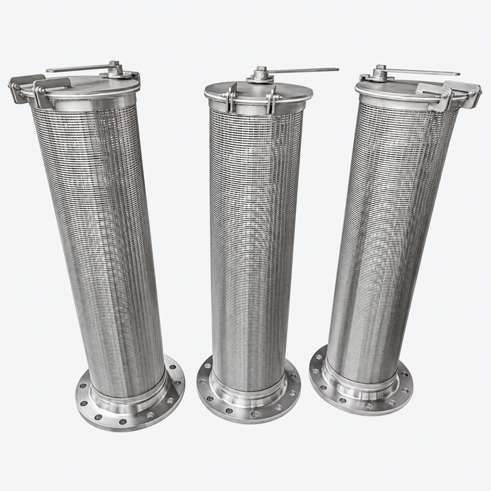 Quick-open end-cap view
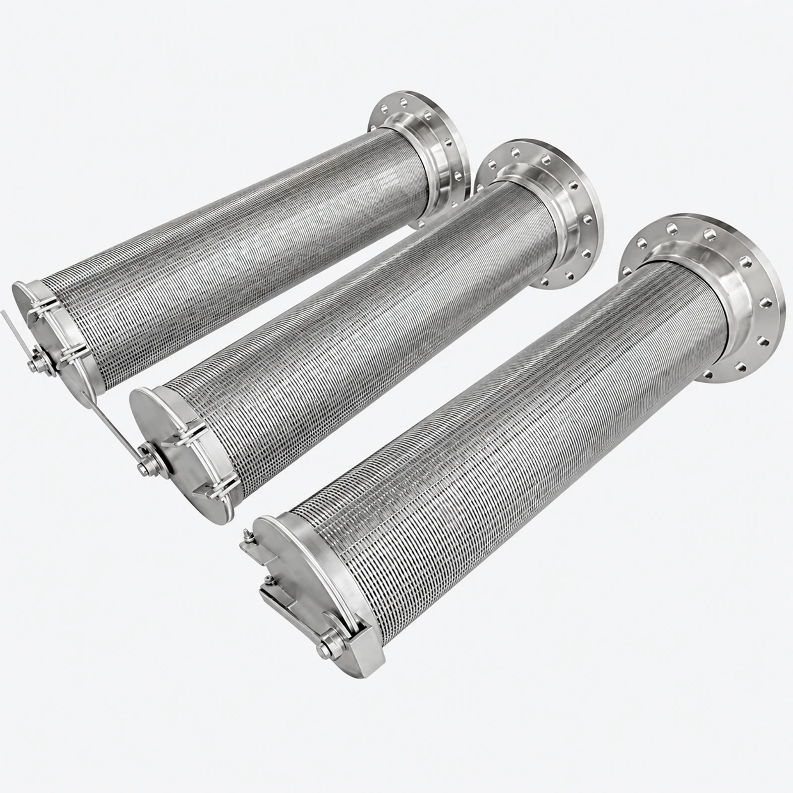 Screen body and closure
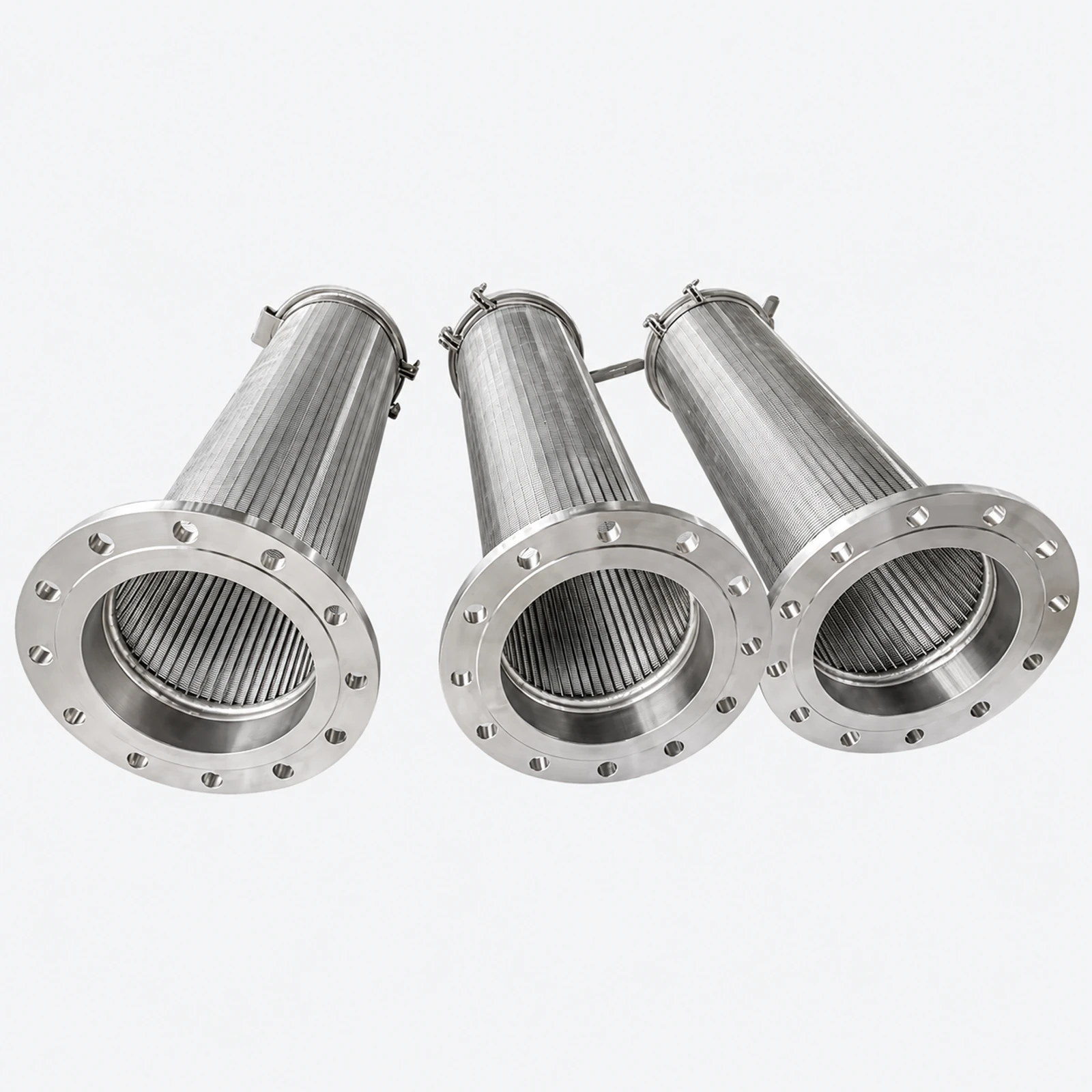 Flange and bore detail
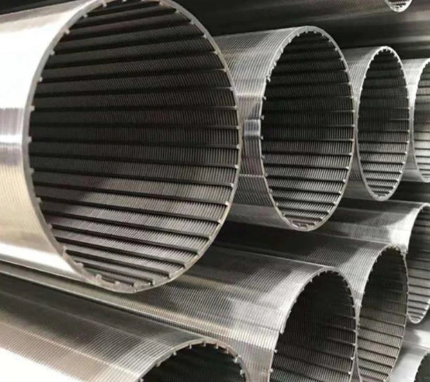 Flanged wedge wire filter cartridges with quick-open end caps
Three flanged wedge wire cartridges showing the removable end closures and slotted screen bodies.
Kaifil manufactures removable wedge wire cartridges with a bolted mounting flange and quick-open access cap. Continuous slots and longitudinal support rods form a rigid screen for water intakes and process liquids.
Slot options include 0.1, 0.2, 0.4, 0.5 and 1.0 mm. Outside diameters of 50–600 mm and screen lengths of 100–3000 mm are combined with profile widths of 1.0, 1.5 or 2.0 mm.
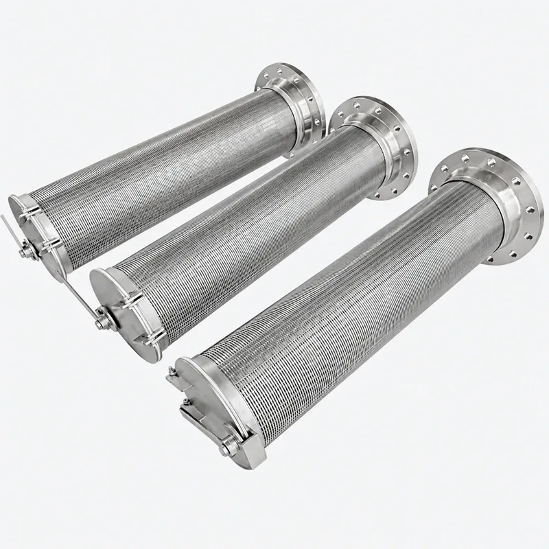
Choose 304, 304L, 316, 316L, duplex 2205 or super duplex 2507. Flanges, bolt patterns, gaskets, hinges and quick-opening hardware are manufactured to the mating equipment and service access.
We configure support rods and reinforcing rings for inside-out or outside-in flow, operating differential pressure and backwashing. Inspection covers slot width, dimensions, flange fit, welds, cap operation and specified material records.
The bolted mounting flange and quick-open cap perform different jobs. The flange locates the cartridge in the equipment; the cap provides service access at the element end. Their sealing faces, gaskets and fastening hardware are listed separately. The bill of materials identifies profile wire, support rods, reinforcing rings, flange, cap and wetted seal; 304/316L and duplex 2205/2507 selections are assigned to each metal component. Installation leaves clearance for both cartridge withdrawal and cap movement, and inspection checks the cap’s closed engagement as well as the screen slots.
| Component / interface | Defined function and inspection |
|---|---|
| Screen body | Profile wire, support rods and selected flow orientation |
| Mounting flange | Bolt pattern, seating face and cartridge position |
| Quick-open cap | Access opening, latch or hinge and closure engagement |
| Separate sealing positions | Flange gasket and access-cap seal |
| Service envelope | Cap movement and complete cartridge withdrawal |
| Screen-body dimension | Numerical selection | Unit | Dimensional boundary |
|---|---|---|---|
| Working-face slot | 0.1 / 0.2 / 0.4 / 0.5 / 1.0 | mm | Continuous-slot opening at the specified active face. |
| Profile face width | 1.0 / 1.5 / 2.0 | mm | Width of the screen wire; support-rod dimensions are separate. |
| Screen-body outside diameter | 50–600 | mm | Screen cylinder diameter; flange and access-cap dimensions are defined separately. |
| Screen-body length | 100–3000 | mm | Screen length; mounting projection and access-cap travel are separate dimensions. |
| Supply item | Order basis |
|---|---|
| Production lead time | 2–3 weeks after order and drawing confirmation. |
| Trial orders | Small trial quantities for fit and process evaluation. |
| Regular production orders | 50 pieces or US$3,000 per order. |
| Quotation basis | Material, finished dimensions, filter construction, connections and quantity. |
| Parameter | Specification | Notes |
|---|---|---|
| Screen construction | Welded continuous-slot wedge wire cylinder | — |
| Working-face slot | 0.1 / 0.2 / 0.4 / 0.5 / 1.0 mm | Continuous-slot opening at the specified active face. |
| Profile face width | 1.0 / 1.5 / 2.0 mm | Width of the screen wire; support-rod dimensions are separate. |
| Screen-body outside diameter | 50–600 mm | Screen cylinder diameter; flange and access-cap dimensions are defined separately. |
| Screen-body length | 100–3000 mm | Screen length; mounting projection and access-cap travel are separate dimensions. |
| Stainless steel options | 304 / 304L / 316 / 316L | Select wetted screen, flange, cap and weld material for the process fluid. |
| Additional alloy option | Duplex 2205 or super duplex 2507 | — |
| Mounting interface | Bolted mounting flange | Provide flange OD, bore, thickness, bolt circle, holes, facing and gasket seat. |
| Access end | Removable quick-open cap | Define latch or fasteners, seal, tether or hinge and opening clearance. |
| Flow direction | Inside-out or outside-in by design | Specify the active slot face and normal/reverse differential-pressure direction. |
| Support structure | Axial support rods; rings or inner support as required | Profile, support pitch and reinforcement follow geometry and load. |
| Pressure and temperature | Designed for specified process conditions | The screen, flange, cap, welds and seals determine the allowable service conditions. |
| Inspection scope | Slot, dimensions, flange, cap and welds | — |
| Supply scope | Screen cartridge with flange and access cap | — |
Materials: 304 / 304L / 316 / 316L / 2205 / 2507 · Special alloys
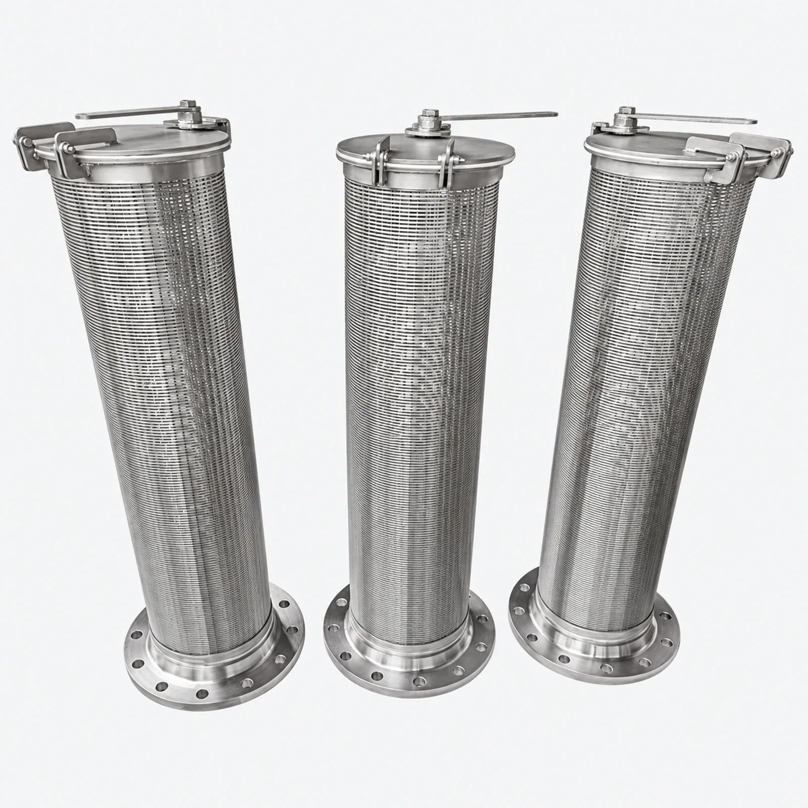
A slotted, removable screen for equipment intake or pre-screening. Select slot, wetted alloy and support arrangement for solids loading and water chemistry.
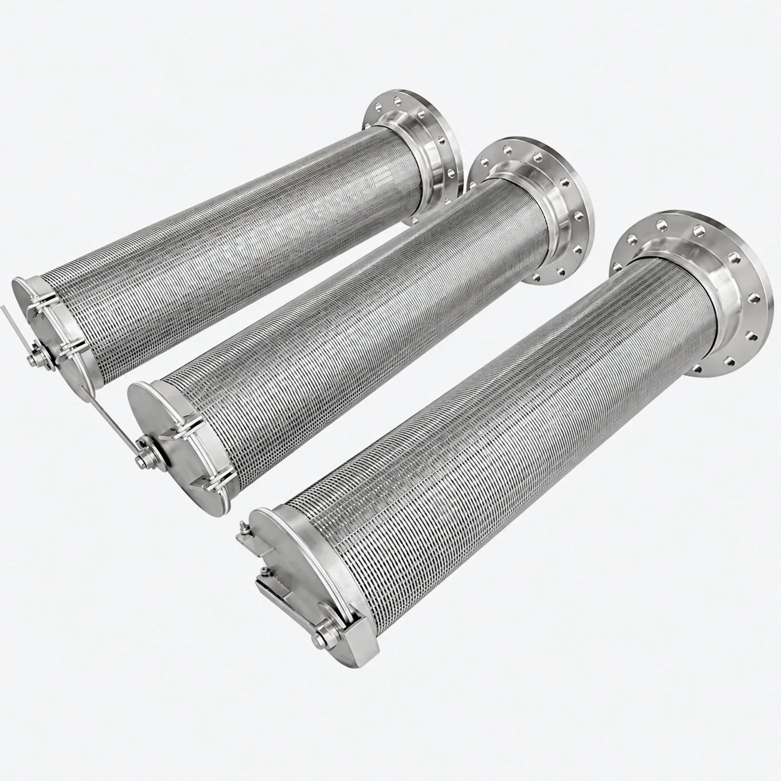
A flanged cartridge can retain coarse process debris ahead of downstream equipment. Confirm hydraulic duty, access space and whether the screen is cleaned in place or removed.
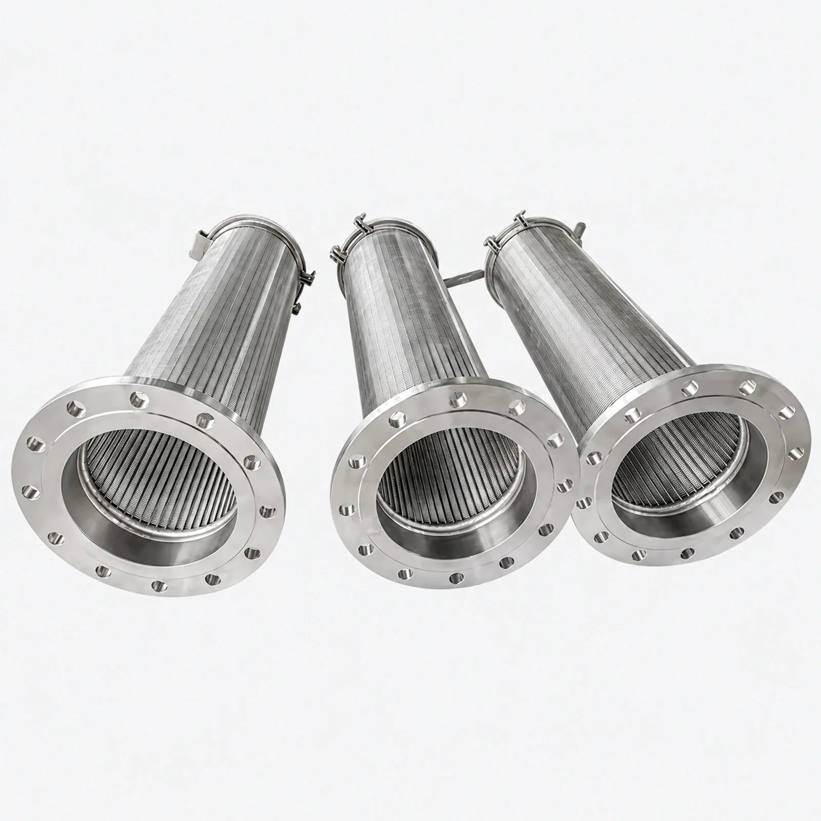
Choose 304, 304L, 316, 316L, duplex 2205 or super duplex 2507. Flanges, bolt patterns, gaskets, hinges and quick-opening hardware are manufactured to the mating equipment and service access.
Include these details when discussing your requirements.
Provide flange OD, bore, thickness, bolt circle, hole number and diameter, sealing face and gasket seat. Include access space for the removable cap.
Position the narrow slot entrance on the incoming-flow side. The slot widens behind the working surface; support rods and reinforcement are arranged for the normal flow and backwash loads.
Explore related products and technical guidance.
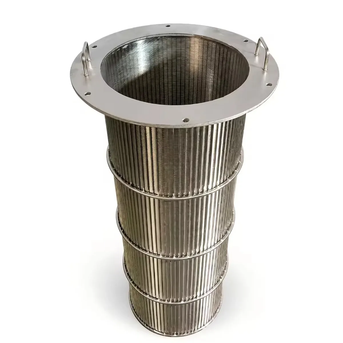
Kaifil manufactures stainless steel flanged filter cartridges with wedge wire, woven mesh, sintered mesh, perforated metal or pleated filtering bodies.
View details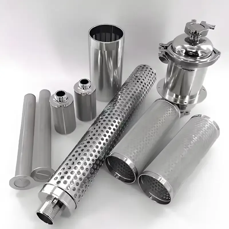
Kaifil manufactures reusable stainless steel sintered mesh cartridges with rigid bonded media, welded seams and threaded, plain-end or O-ring connections.
View details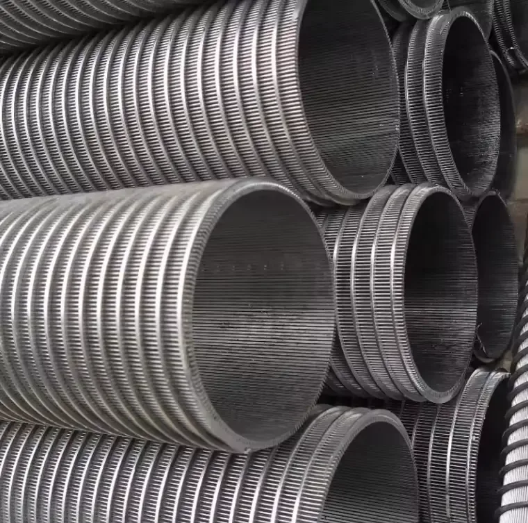
Continuous-slot wedge-wire cylinders provide a rigid screen surface for water intake, resin retention and process separation.
View details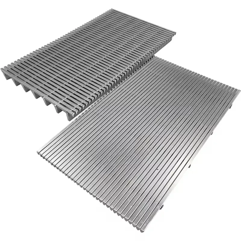
Kaifil manufactures flat wedge wire screen panels with continuous slots, welded profile wires and transverse supports.
View detailsDefine the dimensions, media, joints and inspection records before confirming the order.