Shijiazhuang, Hebei, Chinasales@kaifil.com
KAIFIL
Filter panels and framed screens

Wedge wire screen panels

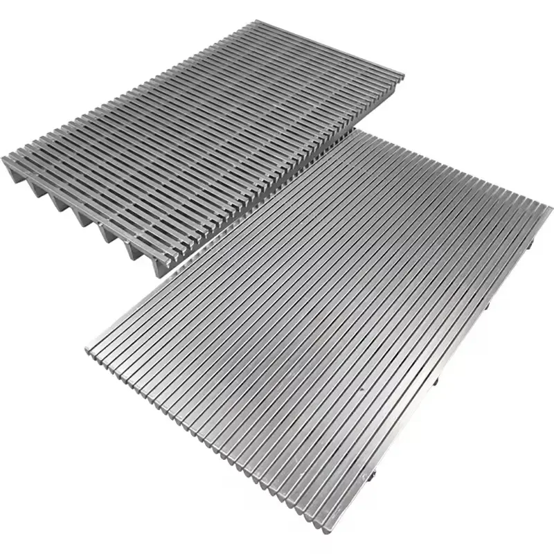
Kaifil manufactures flat wedge wire screen panels with continuous slots, welded profile wires and transverse supports. Choose the slot, surface-wire section, support layout and frame for screening, drainage and media retention.

Wedge wire screens
Working surface
Continuous-slot V-wire screen
Slot opening
0.02–10 mm
Common slot series
0.1–3.0 mm
Stainless steel grades
304 / 316L / 321 / 310S

Share a drawing, reference sample or application requirements to discuss the configuration.

Product details

Welded V-wire creates a continuous-slot surface

Parallel profile wires form the working face and are welded to transverse support members. The broad wire faces carry the material being screened. The passages widen behind the narrow entrance, helping particles that enter the slot pass through the screen. Slot direction and working face are defined with the feed and discharge arrangement.
Select the surface wire and support separately

Surface-wire width determines the amount of metal between adjacent slots. Wire height contributes to the section geometry. Support profiles carry the welded working surface across the mounting span. Choose the surface and support sections separately from the tables, then set their spacing for the panel size, attachment points and service loads.

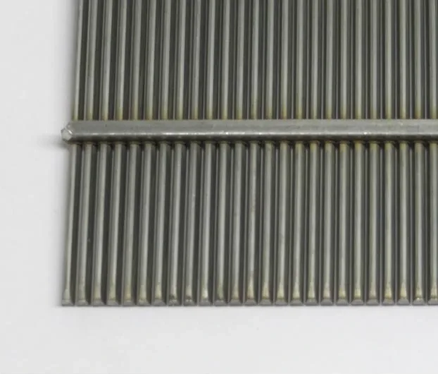
Wedge-wire panel face with transverse support rods
Parallel profile wires form the working slots; perpendicular rods support the welded panel.

Open area from slot and face width

For parallel profile wires, the exposed-face open fraction is slot width divided by slot width plus surface-wire face width. The comparison table shows calculated percentages for three face widths. Frames, supports and mounting features occupy additional area in the installed panel. The panel drawing identifies active screening area and overall footprint separately.

Panel installation, cleaning and inspection

Specify overall length and width, active area, frame section, fixing holes and clamping faces. Include feed direction, fluid, solids loading and vibration or impact loads. Cleaning uses surface rinsing, brushing or reverse flow matched to the installed arrangement. Inspection checks working-face slot width, profile sections, support spacing, flatness, welds and mounting dimensions.

Working face and welded intersections

The broad face of each profile wire forms the screening surface. The narrow section behind it creates a widening passage through the panel. The drawing identifies the working face, slot direction and flow arrow; transverse supports lie on the back. Resistance-welded intersections connect each surface wire to the support members so the panel acts as one rigid screen.

Frames and load transfer

An unframed panel fits into a supporting seat; an edged panel protects the cut wire ends; a perimeter frame provides the fastening interface. Support rods, crossmembers and the equipment seat carry the hydraulic and solids load. The frame drawing fixes the clear span, bearing width, mounting-hole pattern and edge clearance independently of the slot.

Component materials and dimensional control

Specify the alloy separately for profile wires, support rods, edge strips, frame and mounting parts. Their compatibility covers the process liquid and cleaning chemistry. Inspection combines slot measurements across the working face, wire-profile identification, support pitch, panel flatness, squareness, weld attachment and mounting dimensions. The existing profile and open-area tables describe the surface geometry; the frame and supporting members complete the installed design.

Keep the flat working plane and support interface distinct

A flat wedge-wire panel is defined by its active length and width, perimeter and back supports. The profile-wire direction sets the slot direction; the support members locate the working plane relative to the machine seats. Draw the exposed screen area separately from frame and clamping lands.

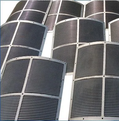
A sieve bend is a separate curved construction with radius, arc angle and a feed tangent. When moving from a flat panel to a curved screen, the machine drawing must include those curved interfaces. For a flat-panel replacement, preserve the existing support contact, working-face direction and access for cleaning.

V-wire, continuous slot and replacement specifications

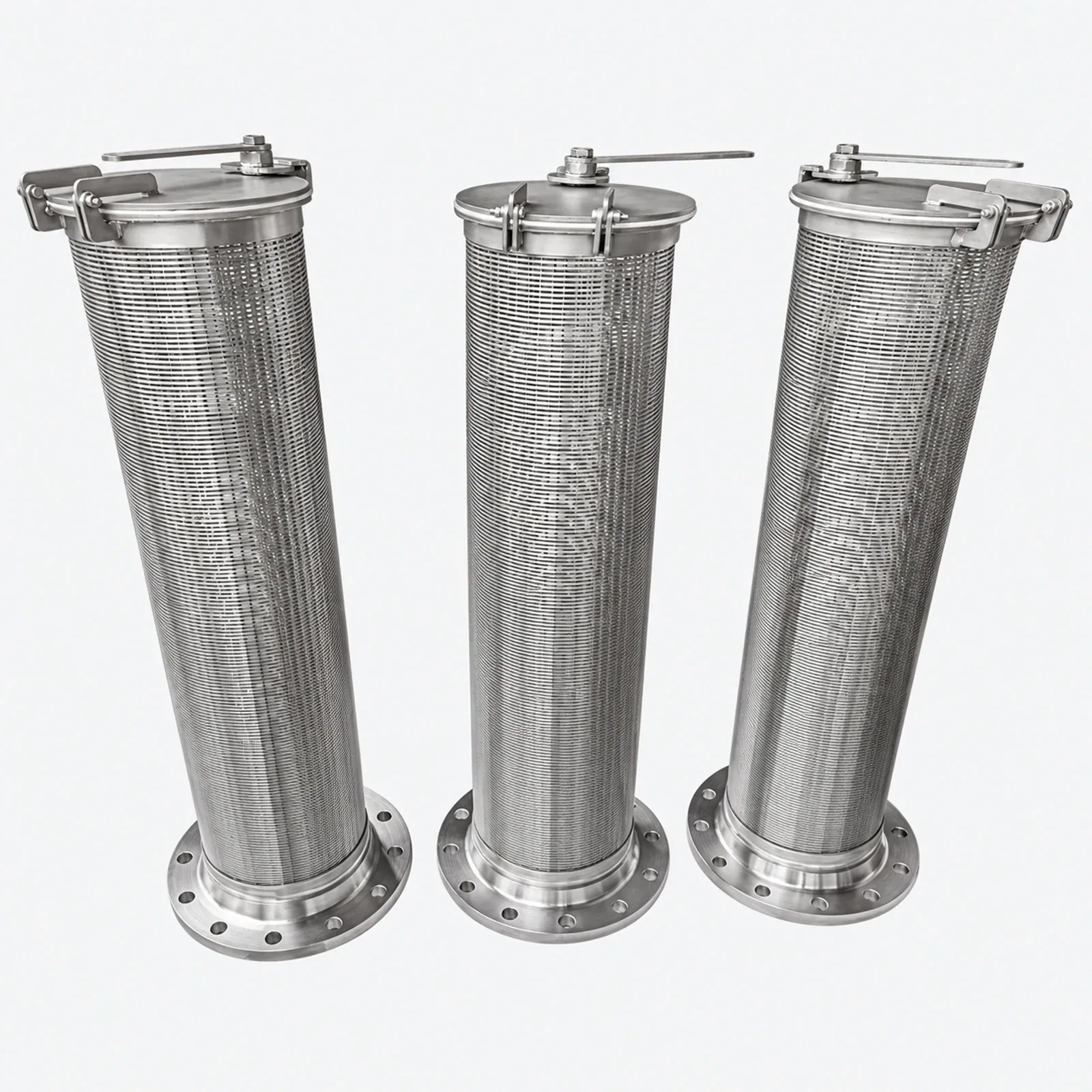
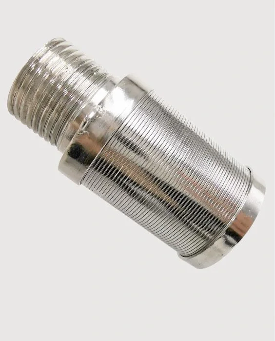
V-wire and continuous-slot screen describe the welded wedge-wire construction. Johnson Screens is a manufacturer’s brand name that also appears in equipment specifications as Johnson screen. A Kaifil replacement panel is defined by its working-face slot, paired profile dimensions, support arrangement and mounting datums. Flat panels, curved sieve bends and cylindrical well screens each retain their own installation geometry.

V-wire surface profiles

V-wire surface profiles

Width is measured across the working face; height is the depth of the profile.

Width (mm)Height (mm)Relief angle (°)
0.81.96.5
1.22.510
1.52.513
1.83.210
1.84.76
2.33.813
3.25.113
3.37.98
Support-profile dimensions

Support-profile dimensions

Select support width and height together, then define spacing and orientation on the panel drawing.

Width (mm)Height (mm)
1.812.7
1.819
1.825.4
2.34
2.33.2
35
36.9
34.7
Calculated exposed-face open area

Calculated exposed-face open area

Open area = slot / (slot + wire face width) × 100%. These percentages describe the exposed wire-and-slot surface.

Slot (mm)1.2 mm face width (%)1.8 mm face width (%)2.3 mm face width (%)
0.17.75.34.2
0.2517.212.29.8
0.529.421.717.9
145.535.730.3
262.552.646.5
371.462.556.6
Panel assembly and installation schedule

Panel assembly and installation schedule

Assembly featureDrawing definition
Screening faceSlot width, profile-wire width and height, working-face orientation
Rear supportsSupport section, spacing datum, direction and unsupported span
Edges and frameCut-edge protection, perimeter profile, bearing width and mounting holes
InstallationPanel outside size, clear opening, seat level, fastener access and flow arrow
Flat-panel working surface and supports

Flat-panel working surface and supports

ComponentTask in the systemDrawing or inspection detail
Working faceForms the continuous-slot surfaceActive length, width and slot direction
Back supportsTransfer load to the mounting seatsProfile, spacing and support contact
Perimeter or frameLocates the panel and its clear windowOverall dimensions, edge seat and clamps
Feed interfacePlaces material on the screening faceApproach direction and cleaning access
Flat-panel working surface and supports
Ordering and production

Ordering and production

Supply itemOrder basis
Production lead time2–3 weeks after order and drawing confirmation.
Trial ordersSmall trial quantities for fit and process evaluation.
Regular production orders50 pieces or US$3,000 per order.
Quotation basisMaterial, finished dimensions, filter construction, connections and quantity.

Structural 3D view

Loading 3D model

Loading 3D model

Drag to rotate · Scroll or pinch to zoom
Download GLB

Explore the welded profile-wire surface and transverse supports. Drag to rotate and scroll to zoom.

Specifications

Wedge wire screen panels
ParameterSpecificationNotes
Working surfaceContinuous-slot V-wire screen—
Slot opening0.02–10 mmMeasured at the working face.
Common slot series0.1–3.0 mm—
Stainless steel grades304 / 316L / 321 / 310S—
Surface-wire sections0.8 × 1.9 to 3.3 × 7.9 mmDiscrete width×height combinations are listed below.
Support spacing10–100 mmThe drawing defines the spacing datum and support direction.
Panel constructionUnframed / edged / perimeter-framed—
Support formsProfile wire / round rod / flat bar / square wire—
Additional alloysS32205 / S32750 / nickel alloys / titanium alloys—
Mounting detailsClamping edges / frames / fixing holes—

Materials: 304 / 316L / 321 / 310S stainless steel; duplex stainless steel, nickel alloys and titanium alloys

Selection guide

Include these details when discussing your requirements.

Set the separation opening
Select nominal slot width and mark the working face and flow direction.
Choose profiles
Select surface-wire width and height, then the support section and spacing.
Define the installation
Provide panel outline, frame, fixing holes, clear span and load direction.
Specify process and cleaning
State fluid, solids, flow, temperature, vibration and cleaning method.

Applications

Dewatering and drainage

Continuous slots drain liquid while the working surface supports the retained solids.

Screening and sizing

Slot width and travel direction define the screening surface for separation equipment.

Media retention

Supported panels retain process media while maintaining a drainage path.

OEM replacement panels

Panel outline, fixing points, profiles and slot direction match the existing equipment.

Frequently asked questions

Where is slot width measured?

Measure the narrow opening between adjacent profile wires at the working face.

How is open area calculated?

Exposed-face open area equals slot width divided by slot width plus surface-wire face width, multiplied by 100%. Installed free area also accounts for supports and frames.

Are surface and support profiles selected as fixed pairs?

Surface-wire and support sections are selected independently, then combined with the required spacing and panel layout.

What should a replacement-panel drawing show?

Include overall dimensions, active area, slot direction, working face, surface and support sections, mounting holes, frame and clamping details.

Technical enquiry

Define the dimensions, media, joints and inspection records before confirming the order.

Technical details (optional)
Selection inputs

WhatsApp

Search