Shijiazhuang, Hebei, Chinasales@kaifil.com
KAIFIL
Filter cups and domed screens

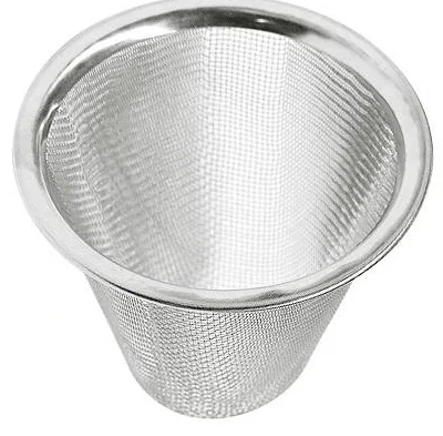
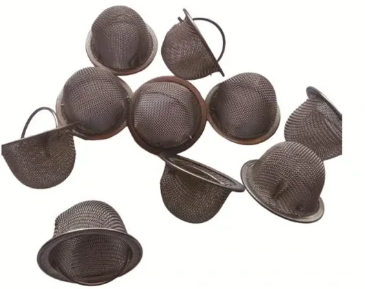
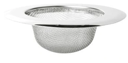
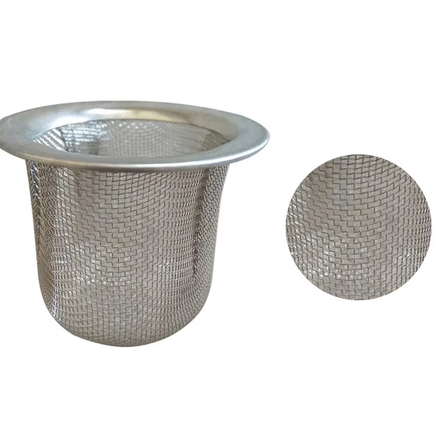
Flanged filter cups

Stainless mesh filter cups with defined flange diameter, contact width, bowl depth and shoulder radius. Integral flanges, retaining rims and layer sequences explained.

Metal wire mesh
Flange
Outside diameter, opening, contact width and flatness
Cup
Body diameter, depth below seating plane and bottom profile
Shoulder
Transition radius, mesh continuity and gasket clearance
Retaining structure
Integral drawn flange or separate rim; clamp and flow direction

Share a drawing, reference sample or application requirements to discuss the configuration.

Product details

Forming and filtering surface

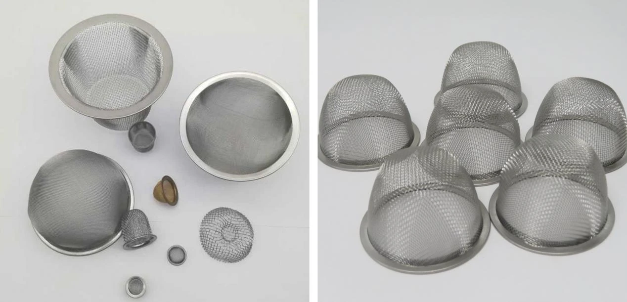
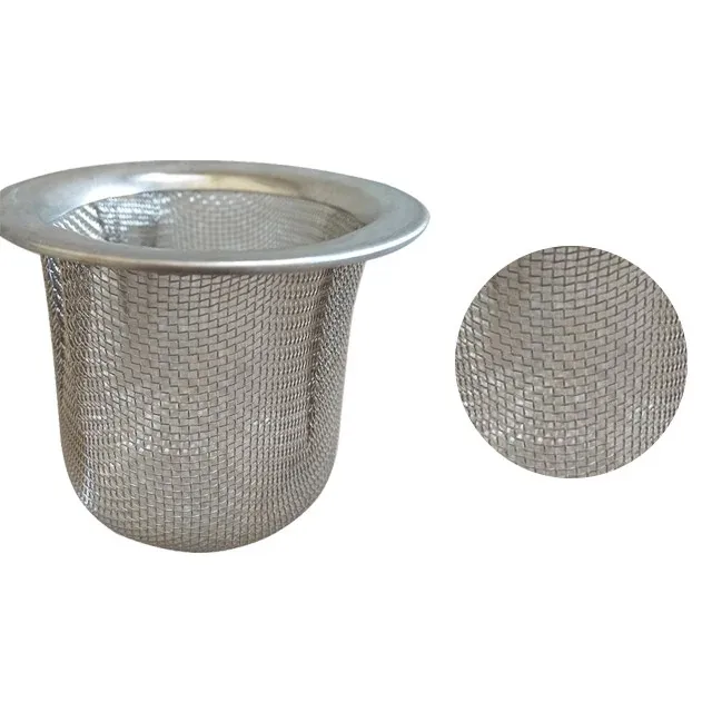
The flange separates the mounting surface from the active cup wall. Its outside diameter, inside opening, contact width and flatness define the axial seat. A flange formed from the mesh blank and a separate metal retaining rim are distinct constructions: the first continues the drawn media, while the second captures the media edge.

Seating geometry and flow path

The transition between flange and bowl is part of the sealing and forming design. Cup depth is referenced to the flange seating plane; the shoulder radius controls the transition into the sidewall. The mating shoulder and clamp retain the flange around its perimeter so flow crosses the cup surface. The drawing marks inlet side, gasket contact and available cover clearance.

Flanged filter cups — Product view

Inspection of the finished part

Specify cloth grade, weave and wire diameter together with the flange or retaining-ring grade. Multilayer cups use an explicit inlet-to-outlet sequence. Inspection checks flange flatness, concentricity of the bowl and flange, shoulder continuity, rim closure and local opening after forming. A component drawing records the bowl and flange as paired geometry.

Treat the projecting rim as a mounting surface

The flange is a projecting cup rim that rests on a matching shoulder. Specify its outside diameter, clear mouth, width and thickness independently from the cup body. The body fits through the seat opening while the rim stays on the support face, giving a defined insertion stop.

Locate the retainer and any gasket on their intended contact bands. The holding load is carried through the rim and seat; the filtering wall keeps its formed profile. Inspect rim flatness, body concentricity and full seating after assembly, then mark the installed flow direction and access for removal.

Separate filtering cloth from the flange seat

The table specifies the starting cloth of the filtering cup. Its open-area figures describe flat cloth; mounting contact bands are defined separately. An integral mesh flange continues the cloth, while a separate retaining ring captures its edge. Inspect the formed shoulder and flange seat alongside the cup wall so the holding surface and exposed filter area remain clearly defined.

Formed component drawing schedule

Formed component drawing schedule

FeatureSpecified dimensions or construction
FlangeOutside diameter, opening, contact width and flatness
CupBody diameter, depth below seating plane and bottom profile
ShoulderTransition radius, mesh continuity and gasket clearance
Retaining structureIntegral drawn flange or separate rim; clamp and flow direction
Treat the projecting rim as a mounting surface

Treat the projecting rim as a mounting surface

Controlled featureInstallation taskCheck on the finished part
Rim outside diameterPositions on the shoulderDiameter and support width
Body and mouthPass through the seat openingClearance and concentricity
Rim thickness and flatnessReceive the holding loadThickness and continuous seating
Retainer and gasketHold and seal the installed cupContact bands, engagement and orientation
Treat the projecting rim as a mounting surface
Flanged cup: starting square-weave cloth combinations

Flanged cup: starting square-weave cloth combinations

Mesh count per inch (warp × weft)Wire diameter (mm)Flat-cloth aperture (mm)Flat-cloth open area (%)
40×400.2540.3836.0
60×600.1910.2330.5
60×600.1780.2533.9
100×1000.1140.1430.3
100×1000.1020.1536.0
Ordering and production

Ordering and production

Supply itemOrder basis
Production lead time2–3 weeks after order and drawing confirmation.
Trial ordersSmall trial quantities for fit and process evaluation.
Regular production orders50 pieces or US$3,000 per order.
Quotation basisMaterial, finished dimensions, filter construction, connections and quantity.

Specifications

Flanged filter cups
ParameterSpecificationNotes
FlangeOutside diameter, opening, contact width and flatness—
CupBody diameter, depth below seating plane and bottom profile—
ShoulderTransition radius, mesh continuity and gasket clearance—
Retaining structureIntegral drawn flange or separate rim; clamp and flow direction—
Material304 / 316L stainless steel—
Finished flanged-cup geometryD × d × H mmD is flange outside diameter; d is body outside diameter; H is body projection below the seating plane. Radial flange projection is (D−d)/2.
Mesh choices40 / 60 / 100 meshThe table pairs the starting 40, 60 and 100 mesh cloth with wire diameter and flat aperture; inspect local openings after forming.
Layer constructionSingle-layer / multilayerDefine each layer and its sequence from inlet to outlet.

Production details and documented projects

Mesh forming
Mesh forming

Mesh forming

A woven-mesh blank is drawn into a shallow bowl while a peripheral flange remains for clamping. A support layer or formed ring can stiffen the lip if repeated removal is expected.

Applications

Clamped filter inserts

The flange provides an axial clamping surface around the active mesh bowl.

Washable inlet screens

The flange seat defines the removal and reinstallation position.

Frequently asked questions

How are the installation dimensions defined?

The transition between flange and bowl is part of the sealing and forming design. Cup depth is referenced to the flange seating plane; the shoulder radius controls the transition into the sidewall. The mating shoulder and clamp retain the flange around its perimeter so flow crosses the cup surface. The drawing marks inlet side, gasket contact and available cover clearance.

What is checked after forming?

Specify cloth grade, weave and wire diameter together with the flange or retaining-ring grade. Multilayer cups use an explicit inlet-to-outlet sequence. Inspection checks flange flatness, concentricity of the bowl and flange, shoulder continuity, rim closure and local opening after forming. A component drawing records the bowl and flange as paired geometry.

Formed cup and mesh-cylinder installation checklist

Complete the component fields and return the sheet with the assembly drawing and order reference.

Download: Formed cup and mesh-cylinder installation checklist

Editable CSV with component dimensions, construction and inspection fields.

Technical enquiry

Define the dimensions, media, joints and inspection records before confirming the order.

Technical details (optional)
Selection inputs

WhatsApp

Search