Shijiazhuang, Hebei, Chinasales@kaifil.com
KAIFIL
Filter cups and domed screens

Deep-drawn mesh filter cups

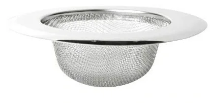
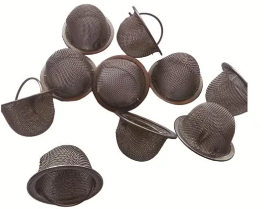
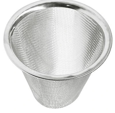
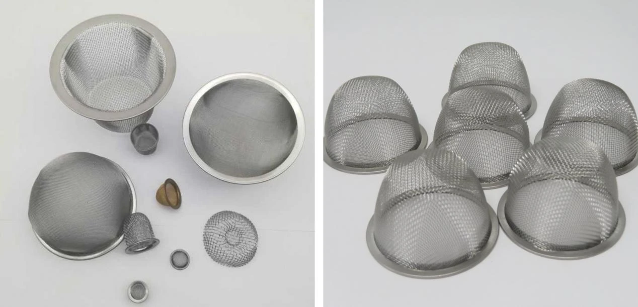
Deep-drawn stainless mesh cups with continuous walls, defined bottom radii and plain, rolled or flanged rims. Compare layer construction and finished-part inspection.

Metal wire mesh
Cup body
Outside diameter, inside opening and wall profile
Drawn bottom
Internal depth and bottom transition radius
Media layers
Weave, mesh count, wire diameter and sequence from inlet to outlet
Rim
Plain, rolled or flanged edge; seating width and retention geometry

Share a drawing, reference sample or application requirements to discuss the configuration.

Product details

Forming and filtering surface

A circular woven-mesh blank is drawn into a cup with a continuous sidewall and rounded transition to the bottom. Drawing redistributes the warp and weft at the shoulder and base. Mesh count, wire diameter and weave identify the starting cloth; the finished opening is measured in the formed wall and high-strain transition. Single-layer and multilayer cups have separately defined layer sequences.
Seating geometry and flow path

Cup depth is measured from the seating plane to the deepest internal point. Body outside diameter, opening diameter and bottom radius describe different features. A plain rim fits a retaining seat, a rolled rim encloses cut wire ends, and a flange provides an axial clamping surface. The housing drawing identifies the active filtering surface and the supported perimeter.

Deep-drawn mesh filter cups — Product view

Inspection of the finished part

Inspection covers depth, roundness, rim flatness, bottom radius, exposed wire ends and mesh continuity. A smooth transition preserves continuous wires around the cup shoulder. For multilayer parts, inspection also checks layer contact and trapped folds. Material allocation names the filtering cloth and any separate retaining ring, with 304 or 316L selected for the process and cleaning medium.

Check the formed profile from the mouth datum

Use the mouth plane as the stated datum for depth and body projection. Match the finished body diameter, bottom radius and insertion space to the equipment cavity. The formed wall and base provide the filtering surface; the mouth and any retaining shoulder position that surface in the fluid passage.

Drawing changes the local mesh geometry at the wall-to-base transition. Inspect the finished radius and wall for damaged wires and interrupted openings, then check mouth shape and depth. Show the pressure-loading direction and backing contact in the installation view so the mesh is supported on the intended side.

Select the blank before drawing the cup

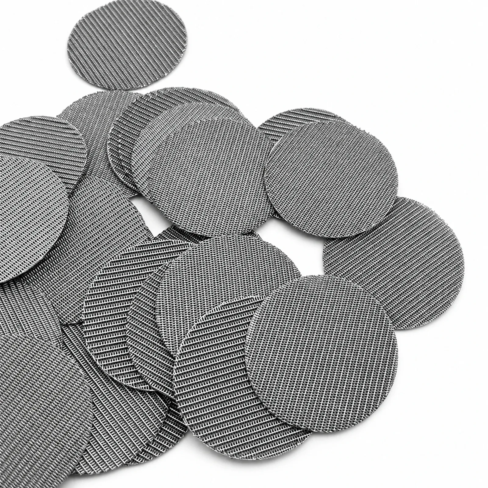
The table pairs the starting flat cloth’s mesh count, wire diameter and aperture. Deep drawing redistributes wires around the wall-to-base transition. Keep each mesh-count and wire-diameter pair together when selecting the blank, then inspect the finished openings in the wall and bottom radius. The rim defines the retained perimeter separately from the exposed filtering surface.

Formed component drawing schedule

Formed component drawing schedule

FeatureSpecified dimensions or construction
Cup bodyOutside diameter, inside opening and wall profile
Drawn bottomInternal depth and bottom transition radius
Media layersWeave, mesh count, wire diameter and sequence from inlet to outlet
RimPlain, rolled or flanged edge; seating width and retention geometry
Check the formed profile from the mouth datum

Check the formed profile from the mouth datum

Controlled featureInstallation taskCheck on the finished part
Mouth datumLocates the cup in its holderMouth diameter, shape and rim plane
Formed bodyProjects into the equipment cavityBody diameter, depth and bottom radius
Wall and base meshProvide the active filtering surfaceWire condition and opening continuity
Backing and retentionSupport and hold the cupLoading direction, contact side and engagement
Check the formed profile from the mouth datum
Deep-drawn cup: starting square-weave cloth combinations

Deep-drawn cup: starting square-weave cloth combinations

Mesh count per inch (warp × weft)Wire diameter (mm)Flat-cloth aperture (mm)Flat-cloth open area (%)
40×400.2540.3836.0
60×600.1910.2330.5
60×600.1780.2533.9
100×1000.1140.1430.3
100×1000.1020.1536.0
Ordering and production

Ordering and production

Supply itemOrder basis
Production lead time2–3 weeks after order and drawing confirmation.
Trial ordersSmall trial quantities for fit and process evaluation.
Regular production orders50 pieces or US$3,000 per order.
Quotation basisMaterial, finished dimensions, filter construction, connections and quantity.

Specifications

Deep-drawn mesh filter cups
ParameterSpecificationNotes
Cup bodyOutside diameter, inside opening and wall profile—
Drawn bottomInternal depth and bottom transition radius—
Media layersWeave, mesh count, wire diameter and sequence from inlet to outlet—
RimPlain, rolled or flanged edge; seating width and retention geometry—
Material304 / 316L stainless steel—
Finished cup geometryD × H mmD is body outside diameter; H is internal depth from the mouth datum.
Mesh choices40 / 60 / 100 meshThe table pairs the starting 40, 60 and 100 mesh cloth with wire diameter and flat aperture; inspect local openings after forming.
Layer constructionSingle-layer / multilayerDefine each layer and its sequence from inlet to outlet.

Production details and documented projects

Mesh forming
Mesh forming

Mesh forming

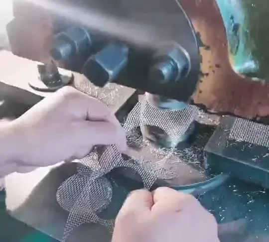
Woven metal mesh is formed over a tool into a cup with a rounded base and sidewall. Available constructions include deep-drawn single- and multilayer metal-mesh parts; forming feasibility depends on weave and drawing depth.

Applications

Small pump inlets

The cup wall and bottom provide a three-dimensional inlet screen inside the pump port.

Appliance inlets

A retained cup removes for cleaning while its seat fixes the installed depth.

Frequently asked questions

How are the installation dimensions defined?

Cup depth is measured from the seating plane to the deepest internal point. Body outside diameter, opening diameter and bottom radius describe different features. A plain rim fits a retaining seat, a rolled rim encloses cut wire ends, and a flange provides an axial clamping surface. The housing drawing identifies the active filtering surface and the supported perimeter.

What is checked after forming?

Inspection covers depth, roundness, rim flatness, bottom radius, exposed wire ends and mesh continuity. A smooth transition preserves continuous wires around the cup shoulder. For multilayer parts, inspection also checks layer contact and trapped folds. Material allocation names the filtering cloth and any separate retaining ring, with 304 or 316L selected for the process and cleaning medium.

Formed cup and mesh-cylinder installation checklist

Complete the component fields and return the sheet with the assembly drawing and order reference.

Download: Formed cup and mesh-cylinder installation checklist

Editable CSV with component dimensions, construction and inspection fields.

Technical enquiry

Define the dimensions, media, joints and inspection records before confirming the order.

Technical details (optional)
Selection inputs

WhatsApp

Search