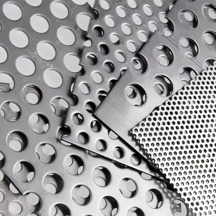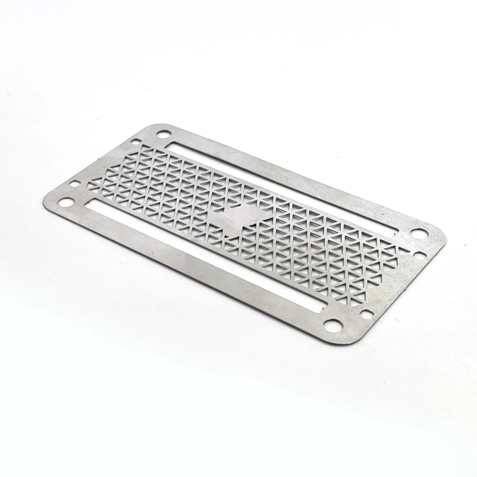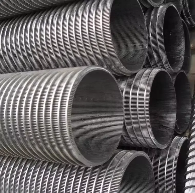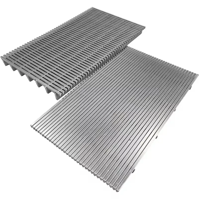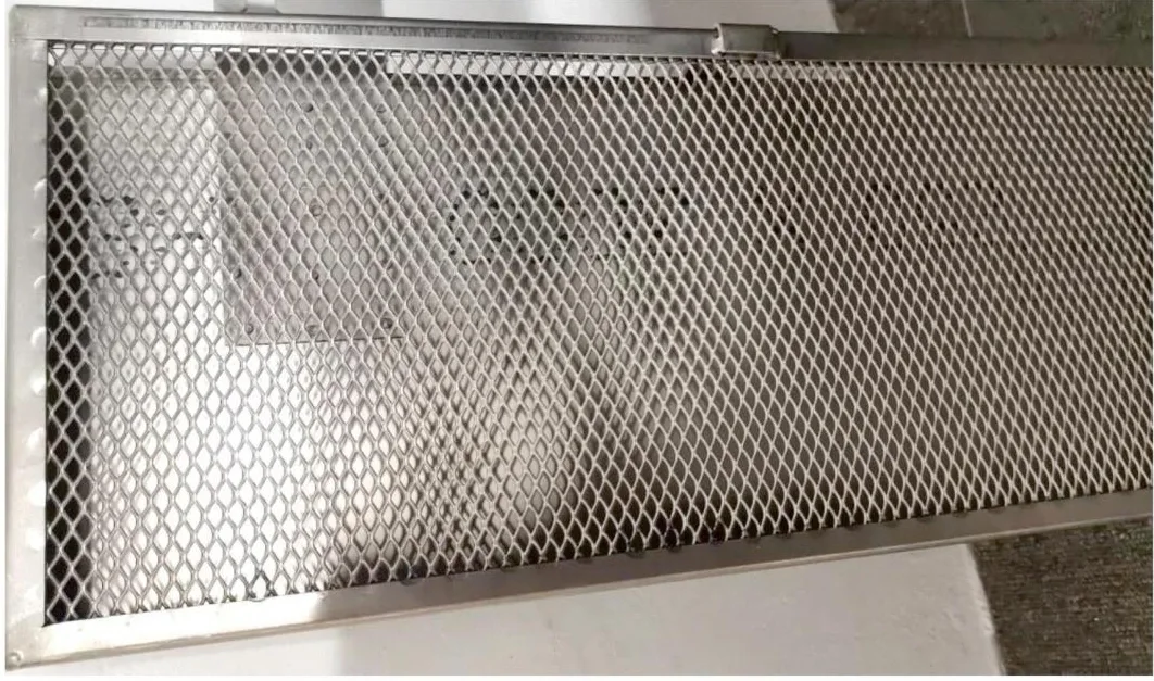
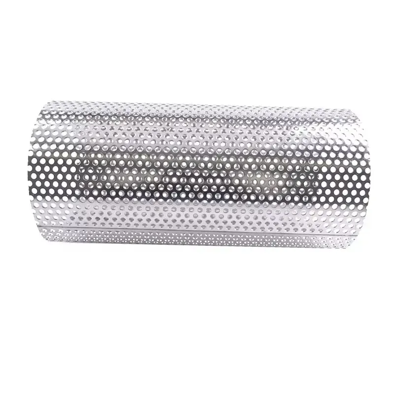
Specify the perforation pattern
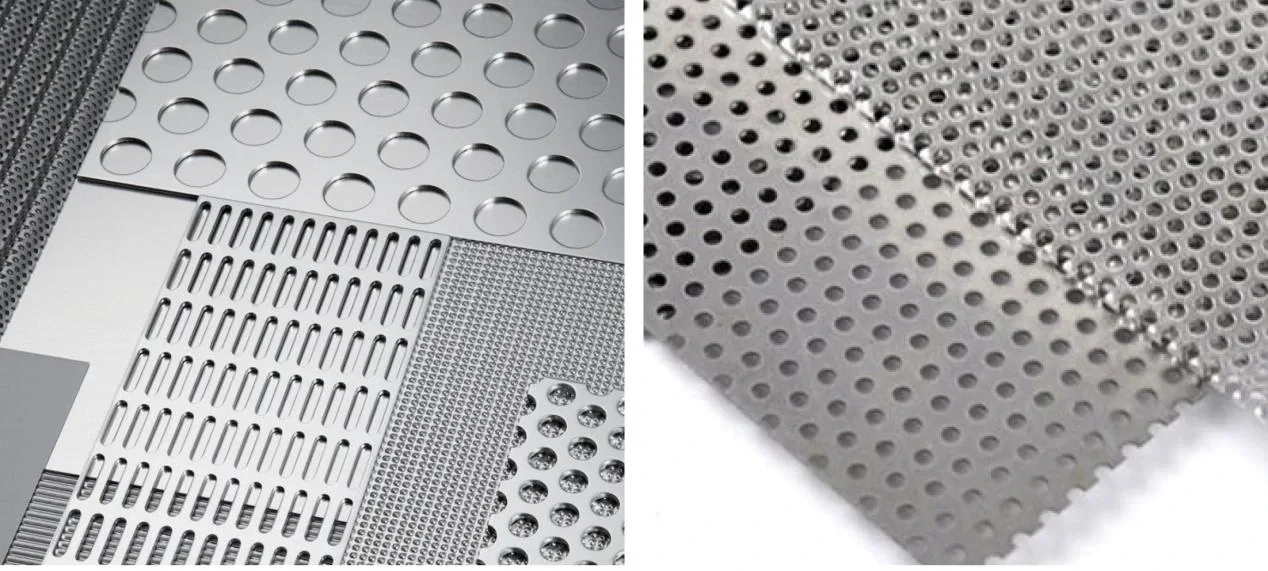
Give hole shape, diameter or slot width, pitch in both directions, layout, sheet thickness and clear border. Theoretical open area follows from opening area divided by repeating cell area.
Check the structural load path
More open area generally leaves less metal between openings. Unsupported span, differential pressure and flow direction affect bending or collapse. Specify support rings or bars where needed.
Allow for blocked area after installation
Frames, gaskets, blank margins and backing structures cover some holes. Compare the free area of the installed assembly, not only the bare sheet.
Design review
Evaluate hole or slot geometry together with sheet thickness, pitch, blank weld margins and unsupported span. A calculated open-area percentage describes the bare pattern; the installed part may lose area beneath frames, gaskets, end caps or a filter medium. Check forward and reverse pressure loading before increasing openness by narrowing the metal ligaments.
Inspection and acceptance
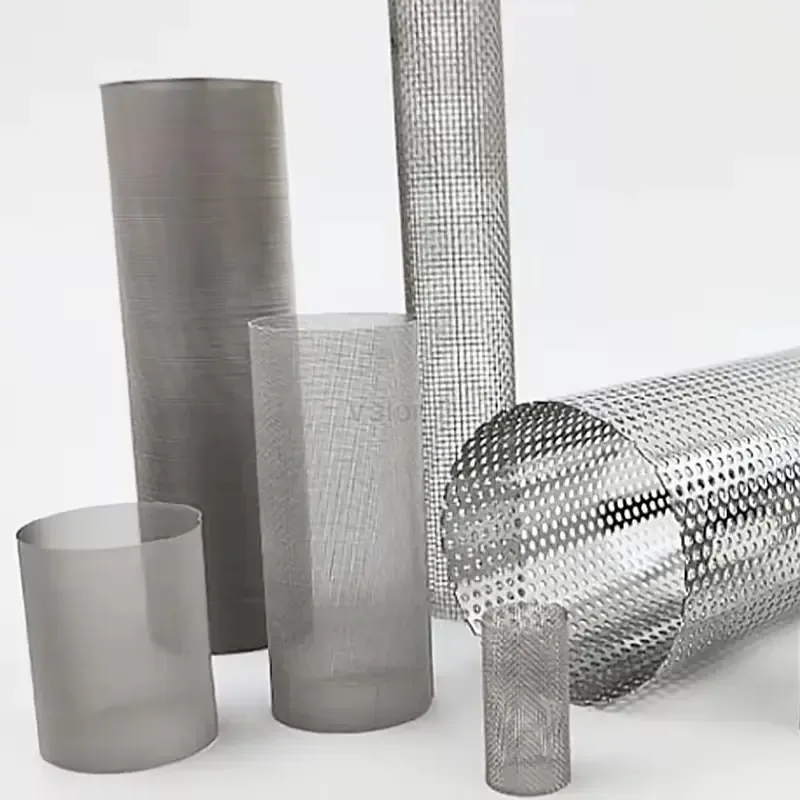
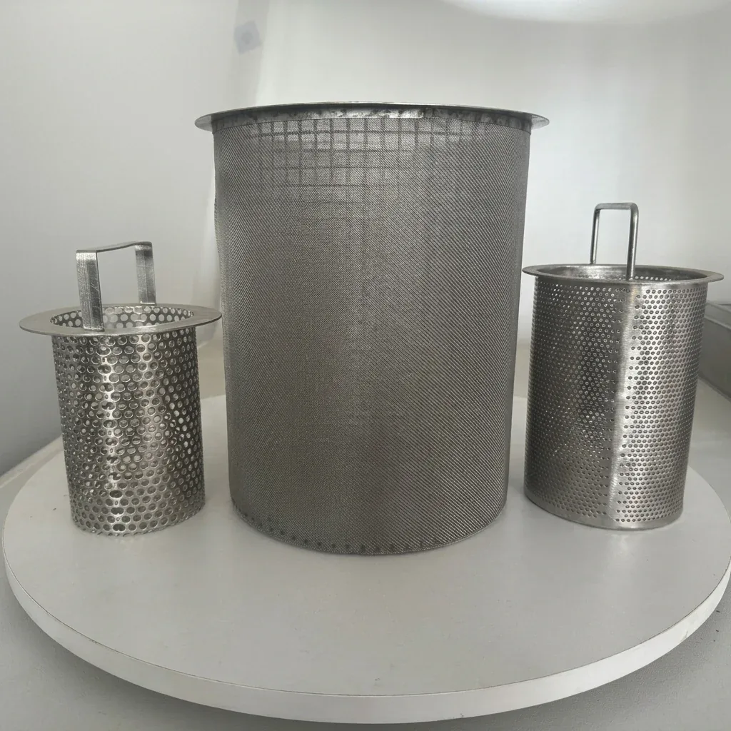
The drawing should show the pattern in both directions, hole tolerance, edge margin, forming direction and the position of every support. Compare the free area of the complete assembly with the required flow path. If a perforated tube supports a finer mesh, the mesh defines retention while the tube carries the structural load.
Worked example
For round holes of diameter d = 3 mm on centre pitch p = 5 mm: square pitch gives open area = πd² / (4p²) × 100 ≈ 28.27%; an equilateral 60° staggered pattern gives πd² / (2√3p²) × 100 ≈ 32.65%. These values apply to the perforated region before margins and supports are deducted. Equal hole diameter does not mean equal free area. Neither calculation establishes allowable pressure or panel stiffness.