Shijiazhuang, Hebei, Chinasales@kaifil.com
KAIFIL
Metal filter cartridges

Sintered Metal Powder Filters

Rigid porous metal tubes, cups and discs made by compacting and sintering metal powder. Select 316/316L stainless steel, bronze or Nickel 200 with a defined media grade, wall geometry and mounting connection.

Sintered metal filters and media
Element forms
Tube / closed-end cup / disc
Fine media grade choices
0.2 / 0.5 / 1 / 2 / 5 / 10 / 20 µm
Porous metal
316 / 316L; bronze; Nickel 200
Mounting
Solid collar / thread / flange / end cap

Share a drawing, reference sample or application requirements to discuss the configuration.

Specifications

Sintered Metal Powder Filters
ParameterSpecificationNotes
Element formsTube / closed-end cup / discEach form has its own mounting drawing
Fine media grade choices0.2 / 0.5 / 1 / 2 / 5 / 10 / 20 µmMedia designation paired with its test basis
Porous metal316 / 316L; bronze; Nickel 200Separate alloy branches
MountingSolid collar / thread / flange / end capJoint and sealing faces defined on the assembly
Tube geometryOD, bore, wall and active lengthFinished dimensions follow the part drawing
Disc geometryDiameter, thickness and supported areaDefine sealing land and support face
Flow directionOutside-in or inside-outMark service and reverse-cleaning directions
Flow characterizationFlow rate and differential pressureState fluid, temperature and exposed area
Acceptance recordsDimensions, joints and agreed media testRecord test conditions with the selected grade
Cleaning routeBackflush / chemical / ultrasonicMethod matched to alloy, deposit and assembly

Materials: 316 / 316L stainless steel, bronze and Nickel 200

Product details

Interconnected pores between bonded particles

Metal powder is shaped and sintered so adjoining particles bond while interconnected voids remain between them. Fluid passes through this three-dimensional pore network. The finished element is a rigid porous body; a woven laminate uses bonded wire layers, and fiber felt uses bonded metal fibers. Each has its own structure and specification.
Media grade and its measurement basis

The fine-grade series includes 0.2, 0.5, 1, 2, 5, 10 and 20 µm media designations. Identify the selected grade together with its pore or particle-retention test, test fluid and acceptance criterion. Pore geometry, particle retention in liquids and particle retention in gases are separate specification fields. A grade number is kept with the corresponding material and wall construction.

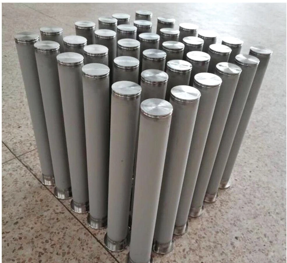
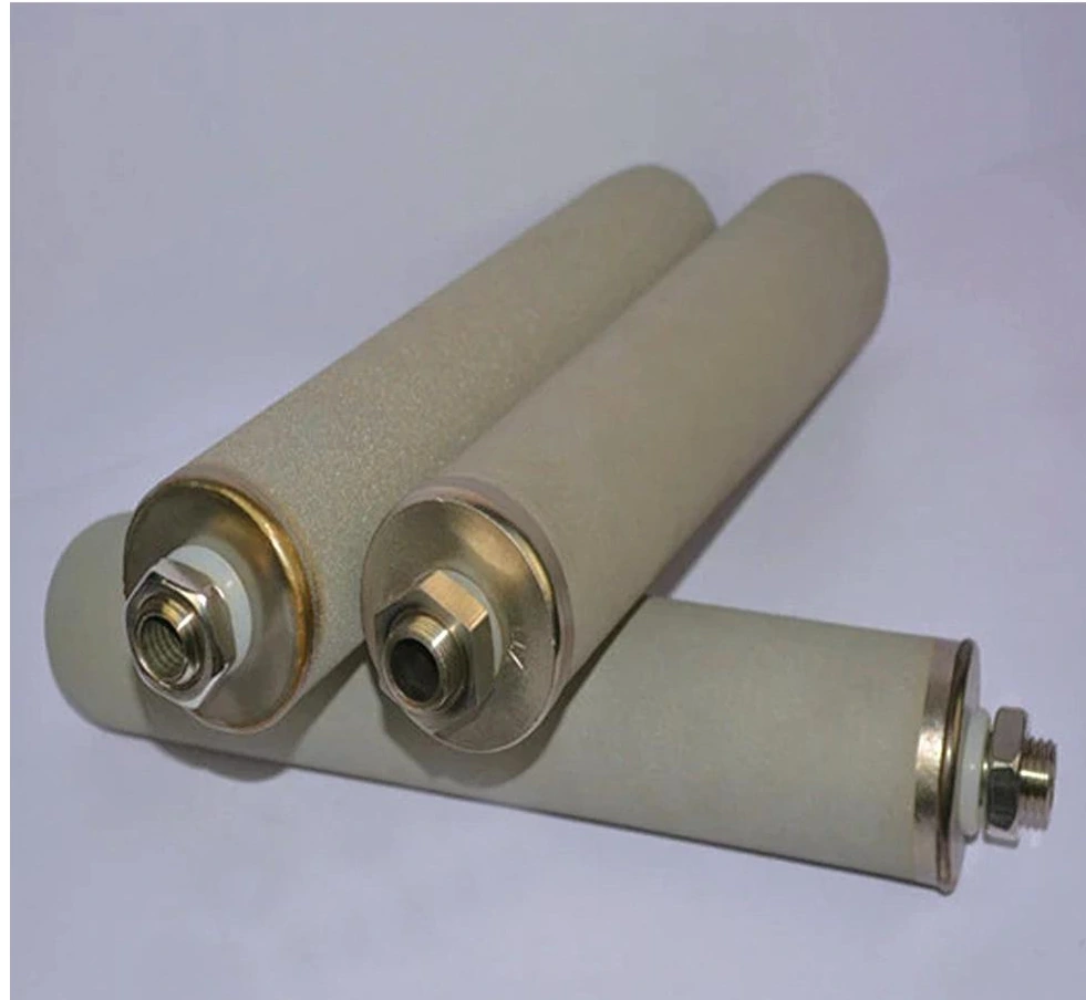
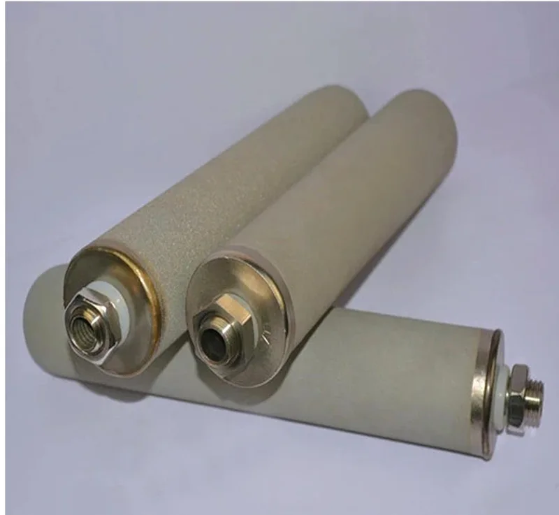
Sintered porous metal tubes with solid end connections
The porous tube and solid mounting fitting form separate regions of the finished assembly.

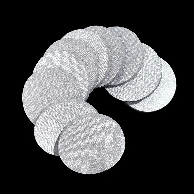
Tubes, closed-end cups and flat discs

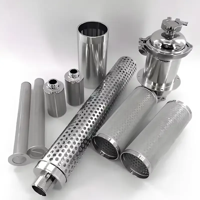
A tube provides a cylindrical wall with defined bore, outside diameter and active length. A closed-end cup adds a porous base and one open connection. A disc seats on a defined support and sealing land. Porous length, solid joining zones and overall dimensions are identified separately so the clean and dirty sides remain separated.

Materials and end connections

316 and 316L stainless steel, bronze and Nickel 200 are separate material branches. Select the metal for the process and cleaning chemistry. Solid collars, threaded fittings, flanges and end caps connect the porous body to its housing. The drawing defines joint position, seal contact, insertion length and the flow direction through the wall.

Flow, loading and support

Permeability is assessed with fluid, temperature, exposed area, wall thickness and differential pressure stated together. Viscous liquids and gases produce different operating conditions. Internal or external support follows the pressure direction and element geometry. Record clean-element flow and pressure drop at a defined operating point for comparison after service.

Cleaning and acceptance

A cleaning route follows the retained material, alloy and joined assembly. Backflushing acts opposite the normal filtration direction; chemical or ultrasonic cleaning uses the specified compatible process. After cleaning, compare flow resistance and the agreed integrity check with the initial record. Finished-part inspection covers dimensions, porous surface, joints, seal faces and identification.

Powder element forms and installation

Powder element forms and installation

FormFiltering regionMounting definitionInspection focus
Open tubeCylindrical porous wallEnd collars and open boreWall, active length and roundness
Closed-end cupPorous wall and baseOne open connectionBase transition and joint
Flat discSupported porous faceSealing land and backingThickness, flatness and active area
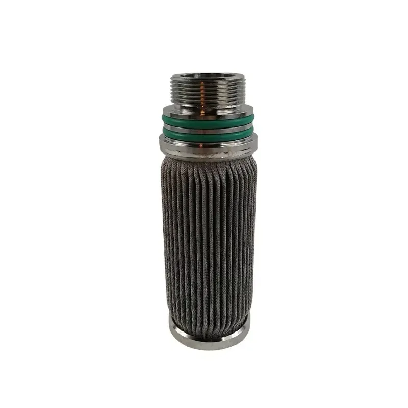
Assembled cartridgePorous body with solid fittingsThread, flange or end closureJoint, seal fit and flow direction
316L seamless porous tubes — selected nominal body geometry

316L seamless porous tubes — selected nominal body geometry

Nominal outside diameter (mm)Nominal inside diameter (mm)Porous tube-body length (mm)Calculated nominal wall (mm)
6.353.175152.41.5875
25.419.05609.63.175

Each row defines one custom 316L seamless powder-sintered tube body. Dimensions are converted using 1 in = 25.4 mm; nominal wall = (outside diameter − nominal inside diameter) / 2. Tube-body length is measured before the added collars and end connections; the assembly drawing defines total length and exposed porous length. Select the media grade and filtration test basis independently for the porous material.

Ordering and production

Ordering and production

Supply itemOrder basis
Production lead time2–3 weeks after order and drawing confirmation.
Trial ordersSmall trial quantities for fit and process evaluation.
Regular production orders50 pieces or US$3,000 per order.
Quotation basisMaterial, finished dimensions, filter construction, connections and quantity.

Applications

Gas filtration inserts

Porous tubes and cups form removable gas-filtering elements with a defined connection and test basis.

Low-flow liquid filtration

A compact porous element combines the required active area and wall thickness for the specified liquid duty.

Instrument and process components

Discs and small porous bodies fit controlled seats for filtration or distribution within a component assembly.

Selection guide

Include these details when discussing your requirements.

Choose the porous structure
Use a powder body for the specified three-dimensional pore network; compare woven laminates and fiber felt as different media.
Define retention and flow together
Pair the grade and test method with the fluid, flow rate, wall thickness, exposed area and allowable pressure drop.
Match the installed form
Select a tube, cup or disc from the housing seat, flow path, support and removal space.
Control the complete joint
Specify porous body alloy, solid fitting, seal contact and joining geometry as one assembly.

Frequently asked questions

How does powder metal differ from sintered mesh?

Powder metal has interconnected pores between bonded particles. Sintered mesh retains the layered geometry of woven wire cloth.

What does a media grade identify?

It identifies a specific porous-media designation. The order pairs it with material, construction, measurement method and the required retention criterion.

Can the same body be used in either flow direction?

The installed drawing defines flow direction, support and joint loading. Service and reverse-cleaning loads are specified separately for the assembly.

Which dimensions define a porous tube?

Specify outside diameter, bore, wall thickness, porous active length, solid connection zones and overall length.

What is checked after cleaning?

Check the porous surface and connections, then compare flow resistance and the specified integrity test with the initial acceptance record.

Technical enquiry

Define the dimensions, media, joints and inspection records before confirming the order.

Technical details (optional)
Selection inputs

WhatsApp

Search