Shijiazhuang, Hebei, Chinasales@kaifil.com
KAIFIL
Filter panels and framed screens

Sieve Bend Screens

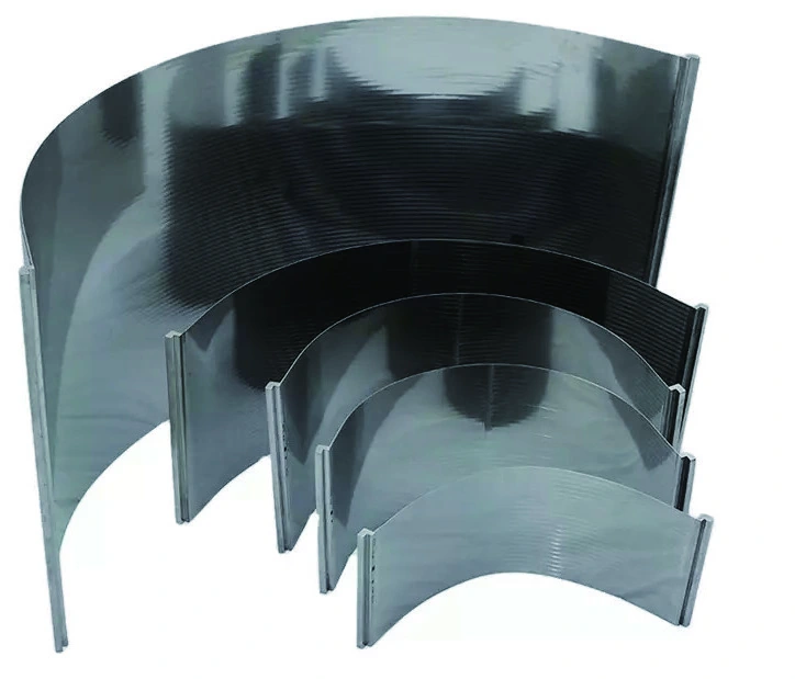
Curved wedge wire sieve bend screens provide a continuous-slot surface for dewatering and solid–liquid separation. Radius, arc angle, working width, slot direction and supports are matched to the feed arrangement.

Wedge wire screens
Screen form
Curved continuous-slot wedge wire panel
Fine-slot series
0.05 / 0.075 / 0.10 / 0.15 mm
Curvature
Radius, included angle and effective arc
Working width
Clear screening width between side boundaries

Share a drawing, reference sample or application requirements to discuss the configuration.

Specifications

Sieve Bend Screens
ParameterSpecificationNotes
Screen formCurved continuous-slot wedge wire panelWorking face defined by radius and included angle.
Fine-slot series0.05 / 0.075 / 0.10 / 0.15 mmDiscrete fine-slot configurations.
CurvatureRadius, included angle and effective arcAll dimensions refer to the working face.
Working widthClear screening width between side boundariesRecord overall width separately.
Slot directionAcross material travelMark the feed direction on the panel drawing.
Back supportCurved support members and mounting seatsKeep the drainage path open.
Metal grades304 / 316LSpecify wires, supports and frame.
InspectionSlot, radius, edge fit and support positionsMeasure the finished curved assembly.
Minimum working-face slot0.025 mmFine-slot curved-screen series; slot measured on the finished working face. Common discrete slots remain 0.05 / 0.075 / 0.10 / 0.15 mm.

Materials: 304 / 316L stainless steel; specify profile wires, supports and frame separately.

Product details

A curved screen with a defined feed path

Feed enters tangentially and travels down the curved working face. Liquid passes through slots running across the travel direction while retained solids continue along the surface. The component is the screening panel; the feed box, collection chamber and supporting machine define its installation.
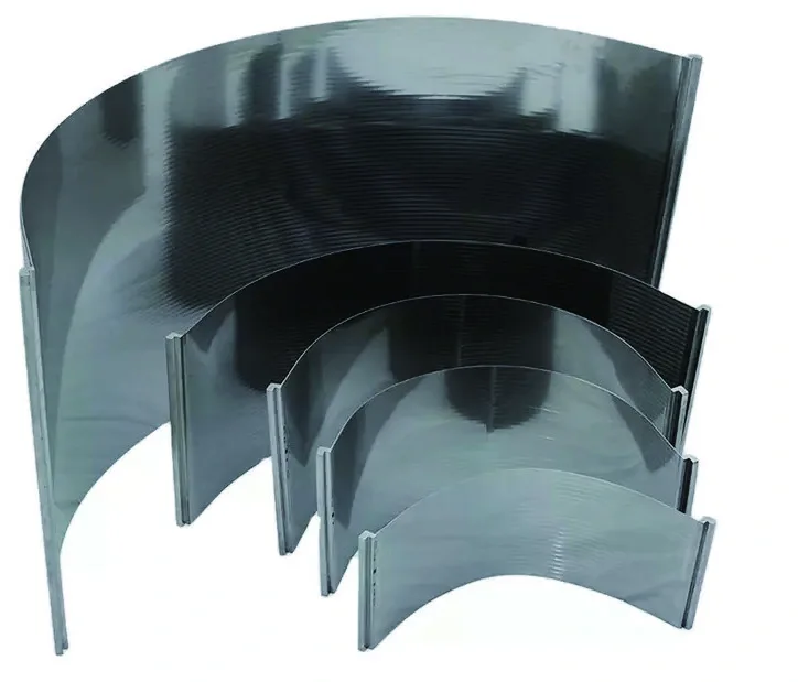
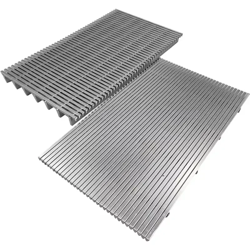
Radius, angle and effective arc

Specify the working-face radius, included angle and effective arc length together. The drawing separates overall width from the unobstructed screening width. End lips, side plates and fixing points locate the panel without covering the intended active surface.

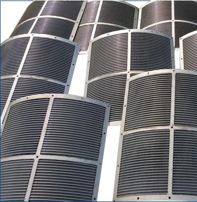
Sieve bend panels showing their curved profile and supporting edges
Radius, arc angle and support positions are dimensioned on the working-face drawing.

Slot and profile construction

Profile wires form the narrow working-face openings and widen the passages behind the face. Fine-slot configurations include 0.05, 0.075, 0.10 and 0.15 mm openings. Slot direction, wire face width and support spacing are recorded as separate construction parameters.

Feed interface and back support

The inlet edge meets the feed box at the specified position and tangent. Supports follow the curved geometry on the back of the panel and connect to the machine seats. The arrangement keeps the liquid collection path open and provides access to both sides for cleaning.

Inspection and replacement drawing

Check slot width at several positions, radius, arc geometry, edge fit and support locations. The replacement drawing includes the machine seats and the feed edge rather than only a flat length and width. Handle the panel at its supports to preserve the working surface and curvature.

DSM screens and curved static screening panels

Sieve bend screen and DSM screen are established commercial names for a curved static screen. Kaifil supplies the wedge-wire panel that fits the screen assembly. Its replacement drawing pairs working-face radius, included arc angle, effective arc length and clear screening width with slot width and wire orientation. Match the inlet edge and feed tangent to the feed box, then define side boundaries, end lips, back supports and mounting-seat positions. The feed box, housing and collection chamber are separate assembly components; the panel drawing defines the supplied screening surface and its installation interfaces.

Curved-screen features and installation interfaces

Curved-screen features and installation interfaces

FeatureScreening roleDrawing definitionAcceptance check
Working faceDrains liquid across continuous slotsSlot, profile and feed directionSlots across the finished face
CurvatureControls the material travel pathRadius, angle and effective arcCurve and inlet tangent
Side and end edgesLocate the active screening areaClear width, lips and mating edgesSeat fit and free area
Back supportsTransfer panel loads to the machineSupport section and seat positionsAlignment and drainage clearance
Fine-slot geometry with a 1.2 mm working-wire face

Fine-slot geometry with a 1.2 mm working-wire face

Slot s (mm)Wire face b (mm)Pitch p = s + b (mm)Calculated face open area (%)
0.051.21.254.0
0.0751.21.2755.9
0.101.21.307.7
0.151.21.3511.1

The four rows use a 1.2 mm wire face and calculate p = s + b and face open area = 100 × s / (s + b), rounded to one decimal place. This is the repeating slot-pattern geometry. Frame overlap, end closures and support footprints are accounted for in the exposed assembly area; hydraulic flow is specified with the process conditions.

Ordering and production

Ordering and production

Supply itemOrder basis
Production lead time2–3 weeks after order and drawing confirmation.
Trial ordersSmall trial quantities for fit and process evaluation.
Regular production orders50 pieces or US$3,000 per order.
Quotation basisMaterial, finished dimensions, filter construction, connections and quantity.

Applications

Mineral and aggregate dewatering

Curved slot panels drain liquid along a controlled feed path in screening equipment.

Pulp and fibre recovery

The screen separates a draining liquid fraction while retained material travels along the curved face.

Starch and process separation

The panel matches the feed box and liquid collection layout for the specified process slurry.

Selection guide

Include these details when discussing your requirements.

Separation duty
Select the opening with the feed solids, particle shape and required drainage.
Feed geometry
Match the inlet tangent and panel arc to the feed-box outlet.
Mounting structure
Locate supports and side boundaries from the machine drawing.
Cleaning access
Provide access to the working face, back and collection passage.

Frequently asked questions

How does a sieve bend differ from a flat panel?

Its working face has a defined radius and arc angle, with feed introduced along the inlet tangent.

Which way do the slots run?

The working slots run across material travel. The drawing marks the feed direction and the active face.

What dimensions identify a replacement?

Working radius, included angle, effective arc, clear width, edges, support seats and feed-interface position.

Is slot width the complete separation specification?

The specification also defines feed properties, profile geometry, inlet arrangement, supports and the exposed screening area.

What should be checked before installation?

Check slots, curvature, edge fit, support locations and clearance for drainage and cleaning.

Curved wedge-wire screen drawing input sheet

Complete the component fields and return the sheet with the assembly drawing and order reference.

Download: Curved wedge-wire screen drawing input sheet

Editable CSV with component dimensions, construction and inspection fields.

Technical enquiry

Define the dimensions, media, joints and inspection records before confirming the order.

Technical details (optional)
Selection inputs

WhatsApp

Search